Direct current power unit

A DC power supply and voltage technology, which is applied in the direction of irreversible AC power input conversion to DC power output, and conversion equipment with intermediate conversion to AC, which can solve problems such as malfunctions and abnormal startup of the system

Inactive Publication Date: 2009-12-30
MITSUMI ELECTRIC CO LTD
View PDF5 Cites 3 Cited by
  • Summary
  • Abstract
  • Description
  • Claims
  • Application Information

AI Technical Summary

Problems solved by technology

[0007] As a result, it is obvious that when the AC adapter plug is pulled out from the outlet and then tur

Method used


Image

  • Direct current power unit
  • Direct current power unit
  • Direct current power unit

Examples


Embodiment approach 1

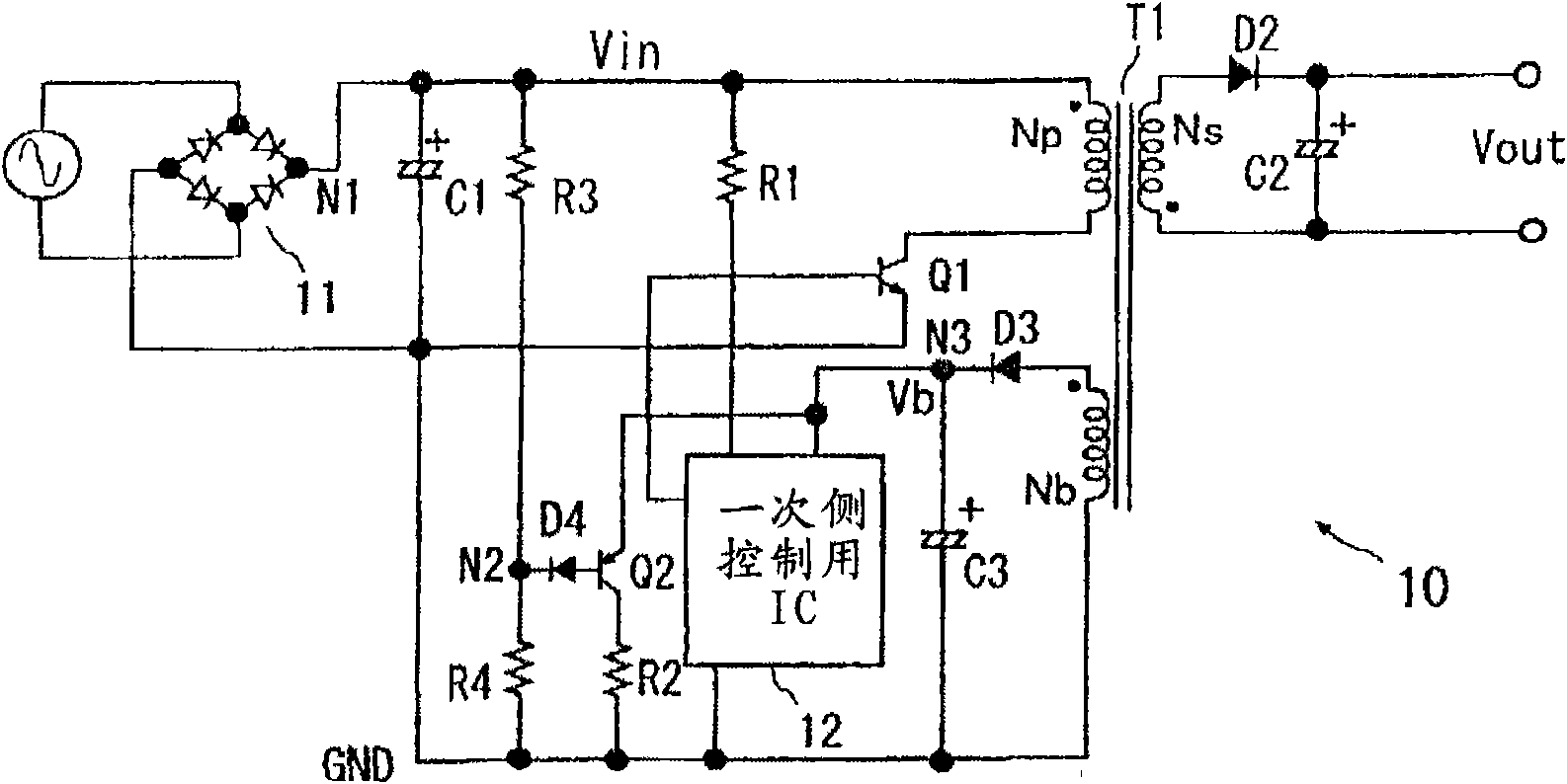
[0039] figure 1 It is a circuit configuration diagram showing the AC adapter according to the first embodiment of the present invention.

[0040] The AC adapter 10 of this embodiment includes: a diode bridge circuit 11 for rectifying an AC voltage (AC) and converting it to a DC voltage; and a filter capacitor C1; A transformer T1 for conversion; a switching transistor Q1 connected in series to the primary-side coil Np of the transformer T1; and a switching control circuit 12 for driving the switching transistor Q1. In this embodiment, the switch control circuit 12 is formed as a semiconductor integrated circuit (hereinafter referred to as a control IC) on one semiconductor chip such as single crystal silicon.

[0041] On the secondary side of the above-mentioned transformer T1, a rectification diode D2 connected in series with the secondary side coil Ns, a smoothing capacitor C2 connected between the cathode terminal of the diode D2 and the other terminal of the secondary si...

Embodiment approach 2

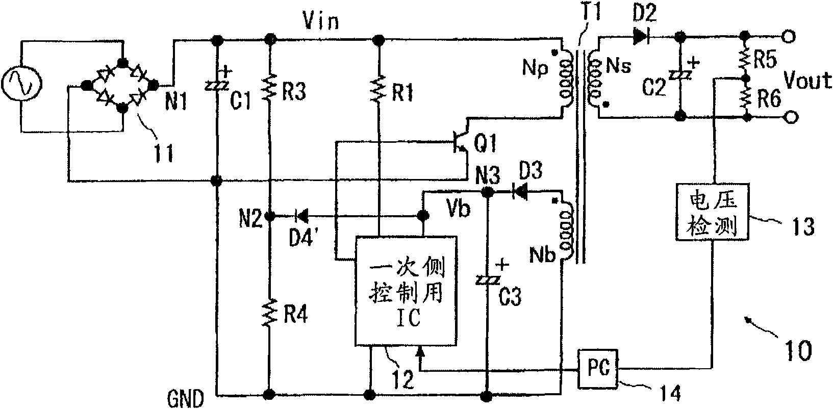
[0052] This embodiment omits the transistor Q2 and its emitter resistor R2 for charge release in the first embodiment, and only provides a diode D4'. When the input voltage Vin drops, the charge of the filter capacitor C3 is transferred to the ground GND through the diode D4'. release, lowering Vb. In this embodiment, the diode D4' operates not as a withstand voltage protection element but as a two-terminal switching element.

[0053] In the case of the above configuration, when the resistance values ​​of the resistors R3 and R4 are the same as in the first embodiment, the voltage Vb of the filter capacitor C3 drops slowly, but the allowable value of the current flowing through the resistors R3 and R4 is large. , or when the falling time of the voltage Vb is not too strict, the resistance value of R4 can be reduced, and the charge of the filter capacitor C3 can be released through the diode D4' as in this embodiment, and the potential Vb of the node N3 can be lowered.

[0054...


PUM


Abstract

The invention provides a direct current power unit for avoiding wrong operation when utilizing IC and guaranteeing normal startup of a system when losing an input voltage and then communicating again. The direct current power unit comprises a transformer (T1) for voltage change with an auxiliary coil; a control circuit (12) for controlling current of a primary side winding of the transformer; and a rectifying circuit (D3) of a rectifying unit and a filter capacitor used for changing alternating current induced in the auxiliary coil into direct current. The control circuit can use a voltage generated by the rectifying circuit as a power supply voltage to work. Voltage stepping units (R3, R4, Q2) are arranged in the direct current power unit. When the input voltage (Vin) of the primary side winding of the transformer is lower than a given potential, a charge in the filter capacitor of the rectifying circuit is released to reduce the voltage supplied to the control circuit.

Description

technical field [0001] The present invention relates to a start-up stabilization technology of an isolated DC power supply device including a voltage conversion transformer, and relates to a technology that is effectively used in a primary-side control circuit used in a power supply device such as an AC adapter, for example. Background technique [0002] The AC adapter is composed of a diode bridge circuit for rectifying AC power, a DC-DC converter for step-down converting the DC voltage rectified by the circuit to a DC voltage of a desired potential, and the like. As the DC-DC converter, for example, a switching power supply device is used which controls the voltage induced in the secondary coil by switching the current flowing in the primary coil of the voltage converting transformer. [0003] AC adapters are being miniaturized and cost-reduced, so it is important to reduce the number of components. For this reason, control ICs have been developed that control the switchi...

Claims


Application Information

Patent Timeline
IPC IPC(8): H02M7/12H02M3/28
Inventor 松尾真也
Owner MITSUMI ELECTRIC CO LTD
Why Eureka
Try Eureka