Method and device thereof for linearly cutting silicon slice
A wire cutting and silicon wafer technology, which is used in sawing machine devices, fine working devices, metal sawing equipment, etc., can solve the problems of large thickness deviation, waste of slice thickness, and different thicknesses, so as to improve the quality of slices and improve the quality of slices. Quantity, the effect of increasing the number and quality of slices
- Summary
- Abstract
- Description
- Claims
- Application Information
AI Technical Summary
Problems solved by technology
Method used
Image

Examples
Embodiment approach
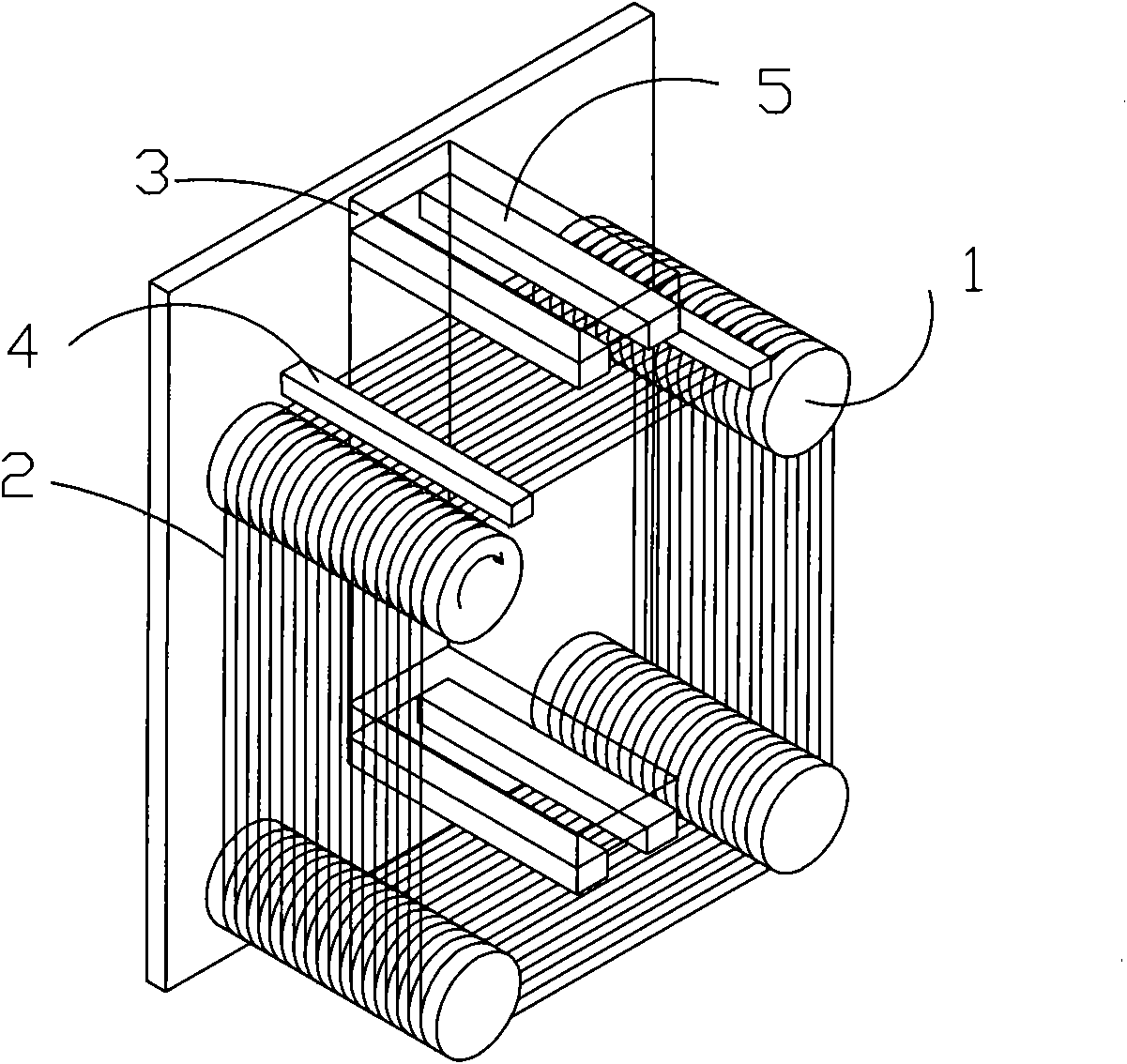
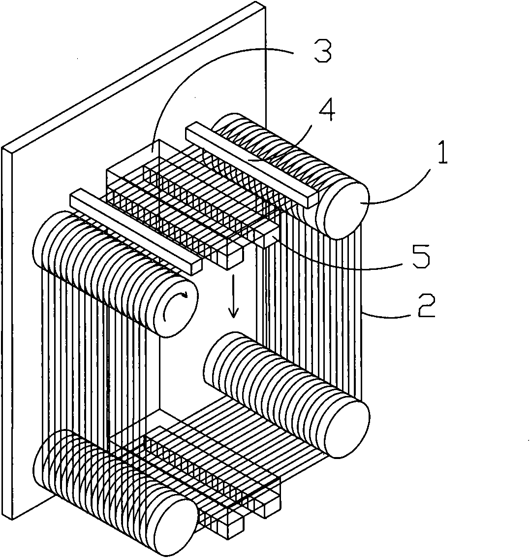
[0032] In the first embodiment, the unequal slot pitch on the guide wheel 1 is along the length of the guide wheel, starting from the first slot where the steel wire is wound on the guide wheel 1, and two adjacent slots The slotting pitch of the steel wire decreases successively, and the reduced slot pitch is adapted to the diameter of the steel wire after the wear of the previous slot.
[0033] In the second embodiment, the unequal slot pitch on the guide wheel 1 is set in sections along the length of the guide wheel, and the number of sections is more than two. There are several wire grooves with the same slot pitch, and the slot pitch on the two adjacent sections decreases sequentially from the first section where the steel wire is wound on the guide wheel 1. Each section decreases the slot pitch It is compatible with the diameter of the steel wire after its previous section is worn. This second embodiment is a preferred technical solution of the present invention.
[0034] In...
Embodiment 1
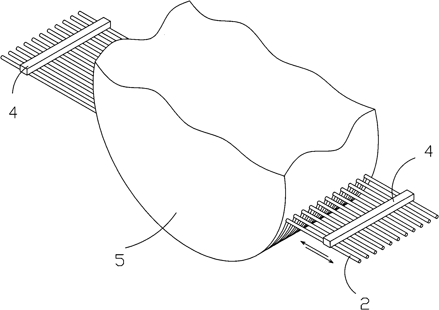
[0036] Such as Figure 4 As shown, the slot pitch on the guide wheel 1 is unequal. It is divided into three unequal slot pitches along the length of the guide wheel. The slot pitch on the two adjacent sections is from steel The first section of the wire wound on the guide wheel 1 begins to decrease sequentially, and there are several wire grooves with equal slot pitch on each section. Such as Figure 4 As shown, in the length direction of the guide wheel 1, it is divided into three unequal slot pitches according to the slot length L1, that is, the slot pitch of the first section A>the slot pitch of the second section B> The slot pitch of the third section C. The slot pitches on the first section A, the second section B, and the third section C are respectively equal.
[0037] Based on the above technical features, the applicant has made improvements on the following types of silicon wafer wire cutting devices:
[0038] A. Existing Swiss MEYER BURGER DS265 guide wheel groove pitch...
Embodiment 2
[0046] Such as Figure 5 As shown, the slot pitch on the guide wheel 1 is unequal. It is divided into 8 unequal slot pitches along the length of the guide wheel. The slot pitch on the two adjacent sections is made from steel The first section of the wire wound on the guide wheel 1 begins to decrease sequentially, and there are several wire grooves with equal slot pitch on each section.
[0047] Based on the above technical features, the applicant has made improvements on the following types of silicon wafer wire cutting devices:
[0048] A. Existing Swiss MEYER BURGER DS264 guide wheel groove pitch structure:
[0049] Slotting length L2 = 820mm, the total number of slots is 2448, and the slot pitch is 0.335mm.
[0050] B. Increase the number of slots after improvement:
[0051] Using Swiss MEYER BURGER DS264 machine, under the condition of slotting length L2=820mm, please refer to Figure 5 , The grooving method is divided into 8 sections of grooving, and the groove pitch of each sec...
PUM
 Abstract
Description
Claims
Application Information
 - Generate Ideas
- Intellectual Property
- Life Sciences
- Materials
- Tech Scout
- Unparalleled Data Quality
- Higher Quality Content
- 60% Fewer Hallucinations
Browse by: Latest US Patents, China's latest patents, Technical Efficacy Thesaurus, Application Domain, Technology Topic, Popular Technical Reports.
© 2025 PatSnap. All rights reserved.Legal|Privacy policy|Modern Slavery Act Transparency Statement|Sitemap|About US| Contact US: help@patsnap.com