Braking cylinder of braking device of railway wagon

A technology of braking device and railway freight car, applied in railway car body parts, brake parts, brake type and other directions, can solve the problems of poor sealing performance, reduced reliability of brake cylinder, shortened service life, etc. The effect of reducing sealing performance, manufacturing accuracy requirements, and prolonging working life

Inactive Publication Date: 2010-01-06
CRRC YANGTZE CO LTD +1
View PDF0 Cites 10 Cited by
  • Summary
  • Abstract
  • Description
  • Claims
  • Application Information

AI Technical Summary

Problems solved by technology

[0003] First, the piston rod of the existing brake cylinder adopts an extrusion-type sealing structure, and the piston rod rubs against the sealing assembly back and forth during motion, which not only causes great wear and poor sealing performance, but also affects the service life of the sealing assembly
At the same time, this structure does not have lateral flexibility
Since the basic brake lever connected with the brake cylinder has the characteristics of arc motion, the parts connected with it will produce lateral displacement, so that the piston rod cannot be directly connected with the basic brake lever, and a push rod needs to be added inside the piston rod. The rod is indirectly connected to the basic brake lever through the push rod, so that there needs to be enough clearance between the outer wall of the push rod and the inner wall of the piston rod to meet the requirements of the circular motion of the basic brake lever, so that the structure becomes relatively complicated
[0004] Second, the existing brake cylinder piston is mainly sealed with a Y-shaped sealing ring,

Method used


Image

  • Braking cylinder of braking device of railway wagon
  • Braking cylinder of braking device of railway wagon
  • Braking cylinder of braking device of railway wagon

Examples


Embodiment Construction

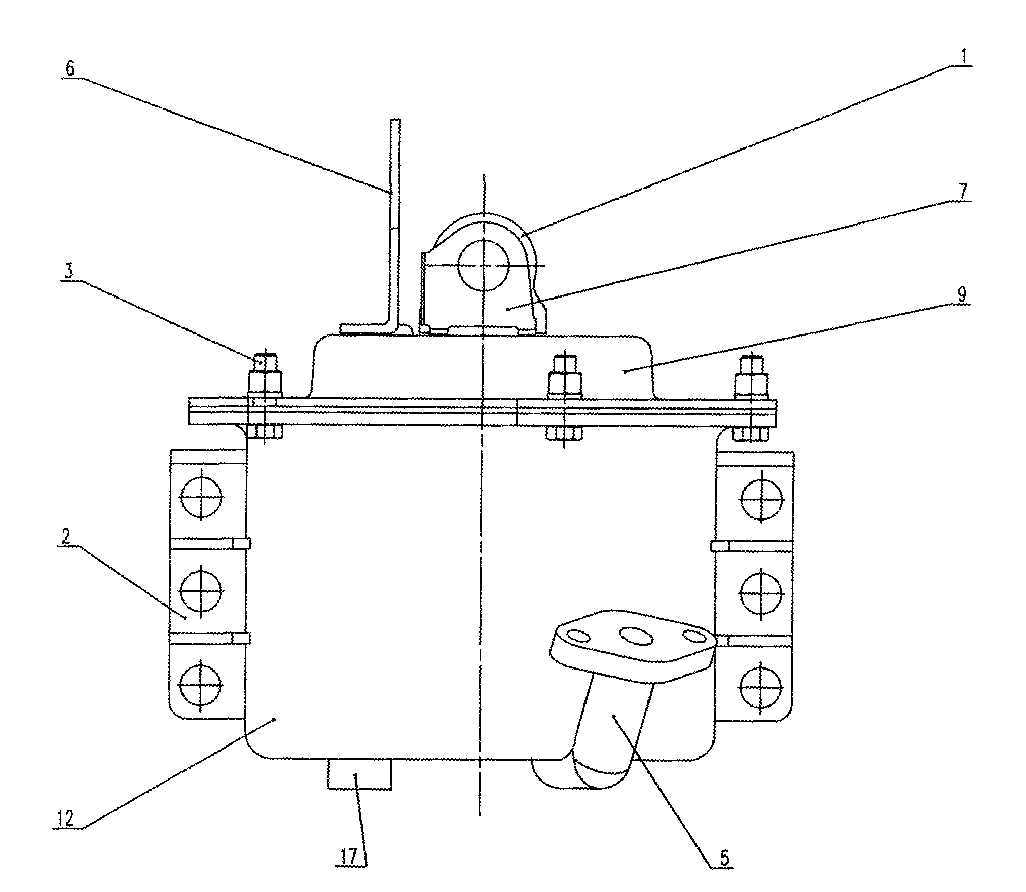
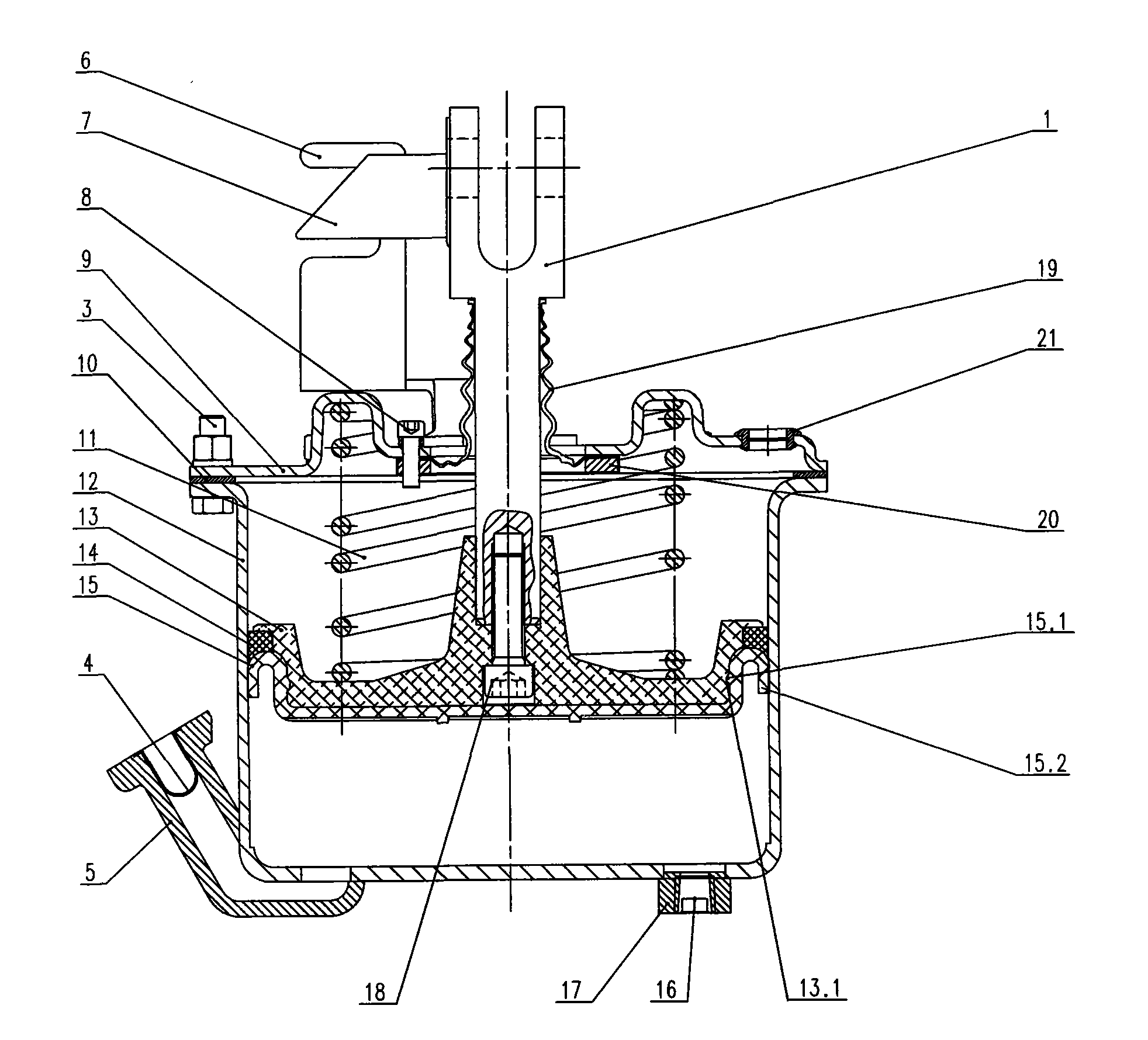
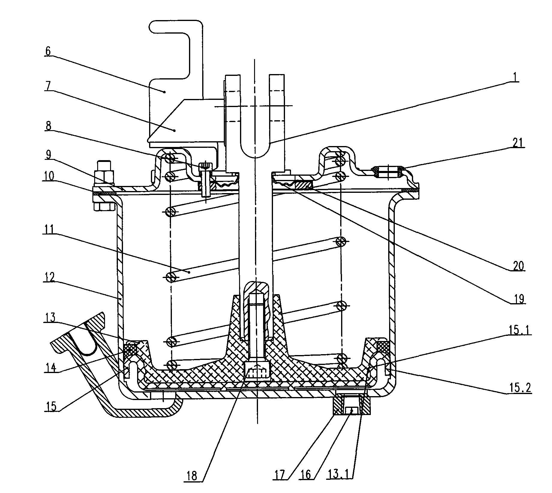
[0016] The brake cylinder of the present invention will be described in further detail below in conjunction with the accompanying drawings and specific embodiments:

[0017] The brake cylinder of the railway wagon braking device shown in the figure includes a cylinder body 12 and a cylinder head 9, and the cylinder body 12 and the cylinder head 9 can be made of stainless steel to improve their corrosion resistance and service life. The cylinder block 12 is made by a spinning process, and is fixedly mounted on the cylinder block 2 . The cylinder head 9 is fastened on the cylinder block 12 through the bolt assembly 3 and the liner 10 . One side of the bottom of the cylinder body 12 is welded with an air inlet and outlet flange elbow 5 , and a dust filter 4 is arranged in the air inlet and outlet flange elbow 5 to prevent dust particles in the air from being sucked in the cylinder body 12 . The other side of the bottom of the cylinder body 12 is provided with a pipe joint 17 for...


PUM


Abstract

The invention discloses a braking cylinder of a braking device of a railway wagon, which mainly solves the problem that the traditional braking cylinder has the disadvantages of large wear loss of components, poor sealing performance and poor working stability. The braking cylinder mainly comprises a cylinder body, a piston arranged in the cylinder body and a piston push rod rigidly connected with the piston together, wherein a flange elbow for air intake and air exhaust is arranged at the bottom of the cylinder body; a release spring is arranged between the piston and a cylinder cover; the upper end of the piston push rod extends out of the cylinder cover; an integral type membrane is covered on the working end surface of the piston; and a sealed space is formed between the integral type membrane and the bottom of the cylinder body, thus the braking cylinder has self-sealing performance. The braking cylinder also has the function of automatically marking the stroke of the piston of the braking cylinder by arranging stroke marks. The invention has the advantages of simple structure, good sealing effect, less wear loss, high reliability and long service life.

Description

technical field [0001] The invention relates to a railway freight car braking device, in particular to a brake cylinder of a railway freight car braking device. Background technique [0002] With the rapid development of railway transportation, the requirements for the braking devices of railway wagons are also getting higher and higher. The brake cylinder is one of the key components of the brake device, and its performance has a great influence on the reliability and service life of the entire brake device. At present, although the main brake cylinders used in domestic railway freight car braking devices can basically meet the service life requirements, there are still the following defects in terms of reliability: [0003] First, the piston rod of the existing brake cylinder adopts an extrusion-type sealing structure, and the piston rod rubs against the sealing assembly back and forth during motion, which not only causes great wear and poor sealing performance, but also ...

Claims


Application Information

Patent Timeline
IPC IPC(8): F16D65/20B61H11/06F16D65/18
Inventor 刘桂军涂智文易立东崔红王高方志坚任志望易新炳
Owner CRRC YANGTZE CO LTD
Why Eureka
Try Eureka