High-precision constant flow source circuit

A constant current source, high-precision technology, applied in the direction of adjusting electrical variables, control/regulation systems, instruments, etc., can solve the problems of low current accuracy and increased application costs

Inactive Publication Date: 2010-01-06
SUPEC SUZHOU
View PDF0 Cites 9 Cited by
  • Summary
  • Abstract
  • Description
  • Claims
  • Application Information

AI Technical Summary

Problems solved by technology

According to the traditional method, the current is realized by dividing the internal reference voltage by the external resistance, such as using a constant current diode or two trio...

Method used


Image

  • High-precision constant flow source circuit
  • High-precision constant flow source circuit
  • High-precision constant flow source circuit

Examples


Embodiment Construction

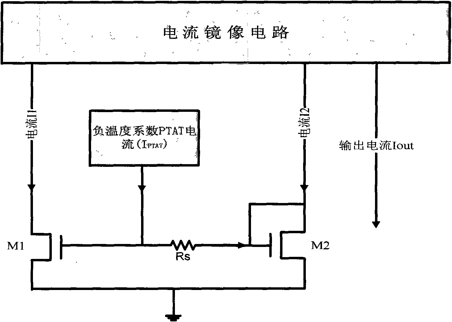
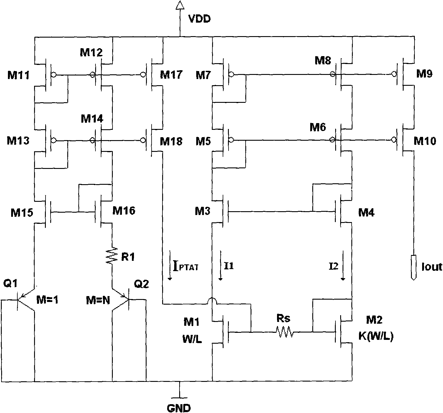
[0018] Such as figure 1 , 2 shows that the high-precision constant current source circuit disclosed in the present invention includes a PTAT (ProportionalTo Absolute Temperature, proportional to absolute temperature) current generation circuit and a core circuit, wherein the PTAT current generation circuit is based on a BANDGAP (bandgap reference) circuit The principle generates a PTAT current with a negative temperature coefficient for use by the core circuit, which is composed of bipolar transistors Q1, Q2, MOS transistors M11-M18 and resistor R1. The circuit produces a current I PTAT Can be expressed as:

[0019] I PTAT = V T · LnN R 1

[0020] where V T is the thermoelectric potential, N is the ratio of the areas of the two bipolar transistors Q2 and Q1, and R1 is a resistor...


PUM


Abstract

The invention discloses a high-precision constant flow source circuit which consists of two parts of a PTAT current generation circuit and a core circuit, wherein the PTAT current generation circuit generates a PTAT current with a certain negative temperature coefficient for the core circuit based on a principle of a BANGAP circuit. The core circuit mainly comprises a control MOS pipe, a positive temperature coefficient resistor and a current mirror image circuit and obtains a high-precision and low temperature coefficient constant current through a certain control relation by utilizing the PTAT current provided by a pre-stage circuit. The invention has the advantages of providing the high-precision and low temperature coefficient constant current for a relevant application occasion, and not only improves the overall performance of the application circuit, but also simplifies a peripheral circuit and reduces the application cost compared with a conventional method. The invention adopts a CMOS process, has good processing compatibility, saves the cost and better meets the requirement of the industrialization production of integrated circuits.

Description

technical field [0001] The invention relates to a constant current source circuit and belongs to the field of analog integrated circuits. In particular, it relates to a high-precision constant current source circuit that generates current with high linear adjustment capability and good temperature characteristics based on CMOS process. Background technique [0002] Constant current with high precision and low temperature coefficient is widely used in clock control, oscillator and other circuits. According to the traditional method, the current is realized by dividing the internal reference voltage by the external resistance, such as using a constant current diode or two triodes of the same type, but the current accuracy of this method is low, and because it is used outside the chip It is realized by discrete electronic components, so the application cost is increased. If this current can be realized inside the chip, the performance of the overall circuit will be greatly im...

Claims


Application Information

Patent Timeline
IPC IPC(8): G05F3/16G05F3/26
Inventor 郑晓一帅柏林
Owner SUPEC SUZHOU
Why Eureka
Try Eureka