Data driver

A technology of data driver and data line, applied in the direction of instruments, static indicators, etc., can solve the problems of high cost and oversized data driver

Active Publication Date: 2010-01-06
NOVATEK MICROELECTRONICS CORP
View PDF0 Cites 5 Cited by
  • Summary
  • Abstract
  • Description
  • Claims
  • Application Information

AI Technical Summary

Problems solved by technology

However, a data driver using circuit elements capable of with

Method used


Image

  • Data driver
  • Data driver
  • Data driver

Examples


no. 1 example

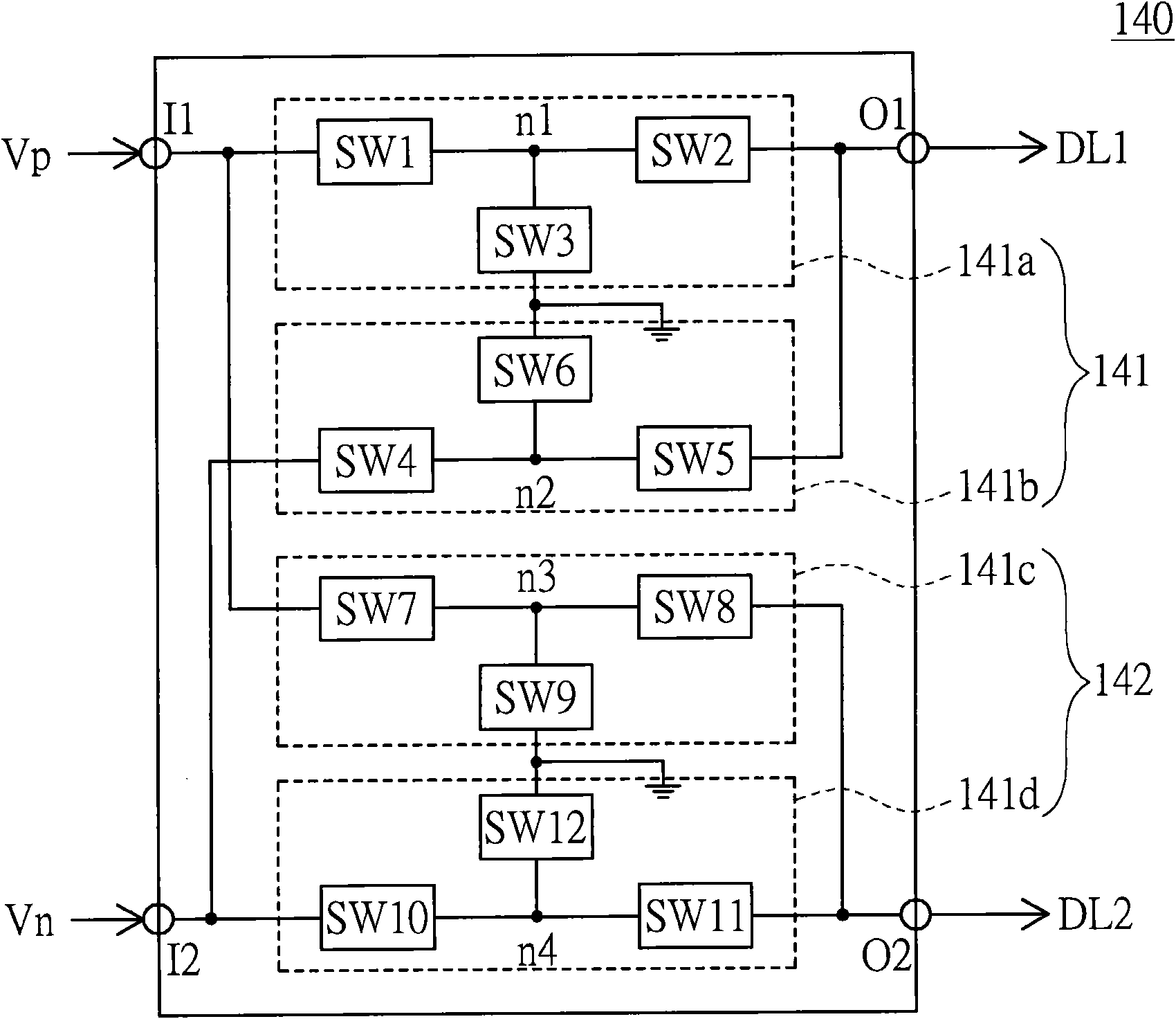
[0023] In this embodiment, the configuration of the multiplexer circuit 140 is improved to reduce the use of circuit components that can withstand high voltage. The multiplexer unit of this embodiment is now described as follows.

[0024] The multiplexer circuit 140 includes m multiplexer units. Please refer to Figure 2A , which shows a schematic diagram of two multiplexer units 141 and 142 of the multiplexer circuit 140 according to the first embodiment of the present invention. The multiplexer unit 141 includes a first input terminal I1, a second input terminal I2, an output terminal O1, a first switch 141a, and a second switch 141b. The first input terminal I1 and the second input terminal I2 are respectively used for receiving the positive pixel voltage Vp and the negative pixel voltage Vn. The output terminal O1 is coupled to one of the data lines DL1˜DL2m, for example, to the data line DL1.

[0025]The first switch 141a has a switch SW1 , a switch SW2 and a switch S...

no. 2 example

[0037] This embodiment is an improved figure 1 The level shifter 121 is configured to reduce the use of circuit components that can withstand high voltage. Now, the level shifter of this embodiment will be described as follows.

[0038] Please also refer to figure 1 and Figure 5A , Figure 5A A block diagram of the level shifter 121 according to the second embodiment of the present invention is shown. The level shifter 121 includes a plurality of level shifting units, for example, four level shifting units LS1 - LS4 . The level shift unit LS1 is used for receiving the second pixel data Dn, and the voltage level corresponding to the second pixel data Dn is a voltage level between a ground level GND and a first positive level PL1 . The level shift unit LS2 is used for adjusting the voltage level of the second pixel data Dn output by the level shift unit LS1 to be a voltage level between a first negative level NL1 and a first positive level PL1 . The level shift unit LS3 i...

no. 3 example

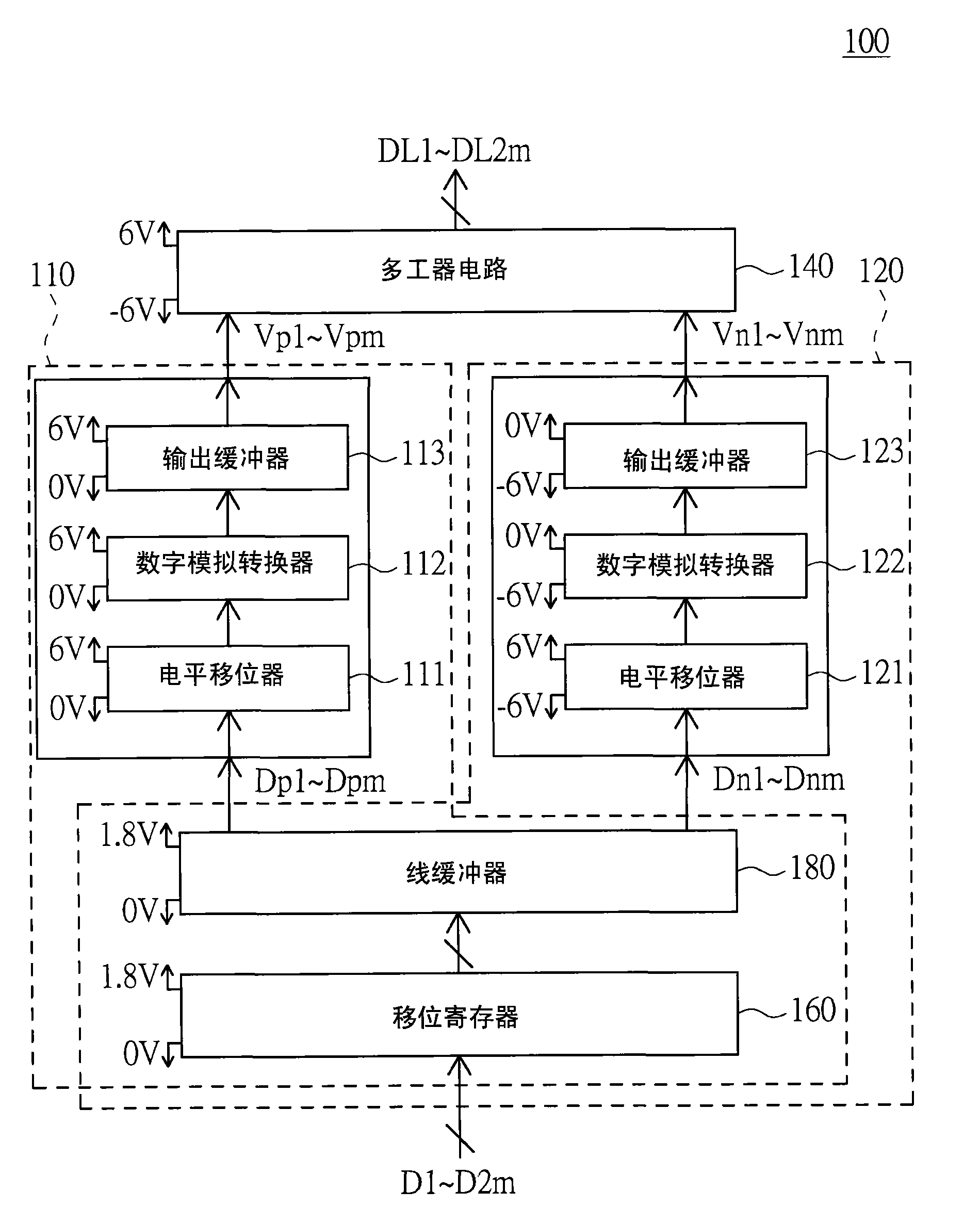
[0045] Please refer to Image 6 , which is a block diagram of a data driver according to a third embodiment of the present invention. The data driver 600 is used to correspondingly drive a plurality of data lines of a display panel according to a plurality of pixel data, and these pixel data include a plurality of first pixel data Dp1˜Dpm (positive polarity pixel data) and a plurality of second pixel data Dn1˜ Dnm (negative polarity pixel data). The data driver 600 includes a first data processing circuit 610 , a second data processing circuit 620 and a multiplexer circuit 640 . The first data processing circuit 610 includes a shift register 612 , a line buffer 613 , a level shifter 614 , a digital-to-analog converter 615 and an output buffer 616 . The first data processing circuit 610 is used for providing a plurality of positive pixel voltages Vp1˜Vpm according to the first pixel data Dp1˜Dpm.

[0046]The second data processing circuit 620 includes a front-stage level shi...


PUM


Abstract

The invention discloses a data driver comprising two data processing circuits and a multiplexer circuit. The two data processing circuits respectively provide a positive pixel voltage and a negative pixel voltage according to first pixel data and second pixel data. The multiplexer circuit comprises a plurality of multiplexer units, a first input end and a second input end thereof receive the positive pixel voltage and the negative pixel voltage, respectively, and the output end is coupled to a data wire. The first and second switches of a first switcher are connected in series between the first input end and the second input end, a node between the two switches is selectively grounded via a third switch. The fourth and fifth switches of a second switcher are connected in series between the second input end and the output end, a node between the two switches is selectively grounded via a sixth switch. When the first and the second switches are turned on, the sixth switch is turned on. When the fourth and fifth switches are turned on, the third switch is turned on.

Description

technical field [0001] The present invention relates to a driver, and in particular to a data driver. Background technique [0002] In the driving mode of the liquid crystal display, in order to avoid damaging the physical properties of the liquid crystal molecules, voltages of different polarities must be used in turn to drive the liquid crystal molecules. In the driving method using a fixed common voltage, the data driver switches the polarity of the output voltage to properly drive the liquid crystal molecules. [0003] Conventionally, when the data driver drives the liquid crystal molecules, the level range of the driving voltage is about -6V to 6V. At this time, the maximum cross voltage that the circuit elements used in the data driver need to withstand may be 12 volts (-6~6 volts). In order to withstand the 12V cross-voltage during the driving process of the liquid crystal display, the data driver must use circuit elements capable of withstanding high voltage. Howe...

Claims


Application Information

Patent Timeline
IPC IPC(8): G09G3/36
Inventor 彭昱勋何锡锜黄立群
Owner NOVATEK MICROELECTRONICS CORP
Why Eureka
Try Eureka