Buckling-resistant lift cylinders

A technology for lifting and lowering cylinders and cylinders, used in lifting devices, fluid pressure actuating devices, plungers, etc. Effect

Inactive Publication Date: 2014-09-17
RAYMOND LTD
View PDF0 Cites 2 Cited by
  • Summary
  • Abstract
  • Description
  • Claims
  • Application Information

AI Technical Summary

Problems solved by technology

However, there is a design tension between providing a short overall forklift length and providing a high lift height

Method used


Image

  • Buckling-resistant lift cylinders
  • Buckling-resistant lift cylinders
  • Buckling-resistant lift cylinders

Examples


Embodiment Construction

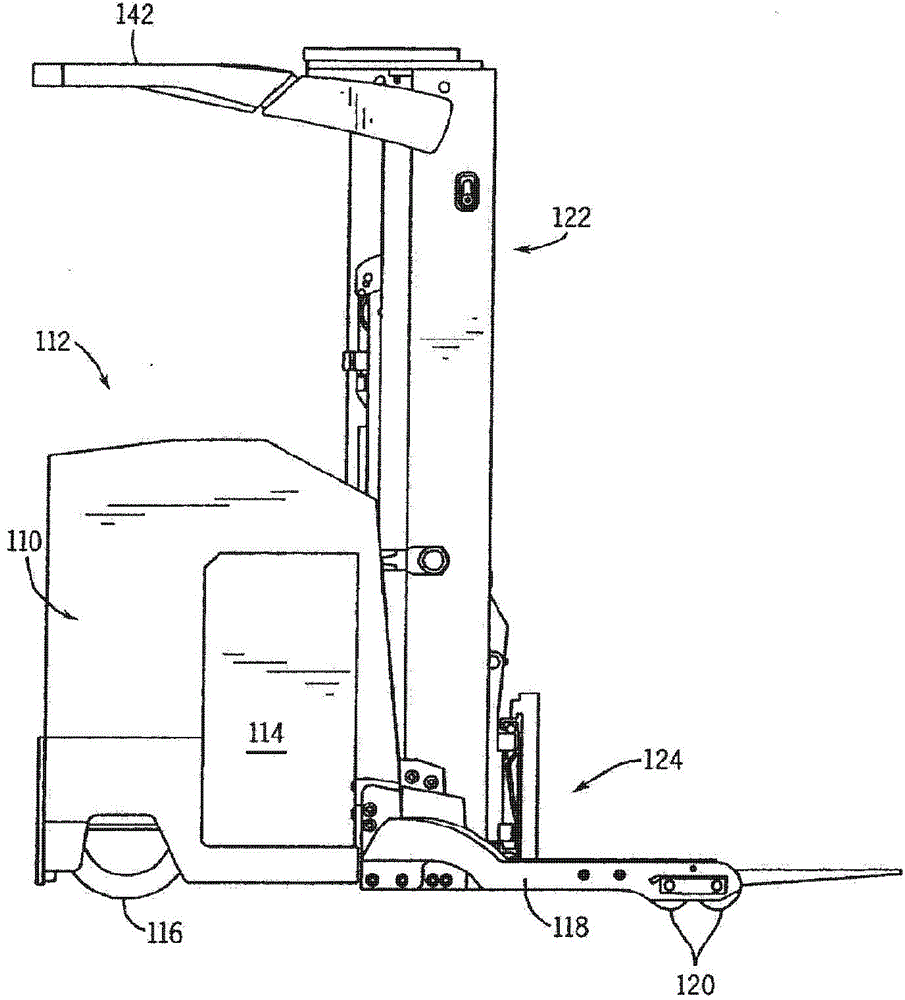
[0021] First refer to figure 1 , the exemplary lift truck includes a power unit 110 having a driver compartment 112 at the rear and a battery compartment 114 at the front. The battery powers a traction motor drive (not shown), which turns steerable drive wheels 116 to propel and steer the forklift. A pair of laterally spaced base legs 118 are indirectly connected to and extend forwardly from the power unit 110, and each base leg 118 includes wheels 120 for supporting a forklift. A mast assembly 122 is connected to the front end of the power unit 110 and extends vertically upward therefrom. The mast assembly 122 supports a fork carriage 124 that is used to lift or hoist objects to various heights.

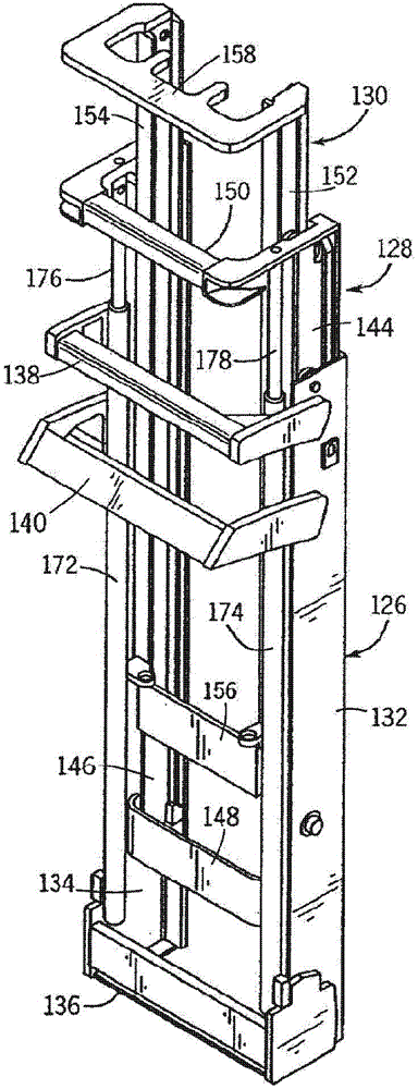
[0022] Now refer to figure 2 , the mast assembly 122 consists of three telescoping sections (although other numbers of sections could be used). These include a base portion 126 , an outer telescoping portion 128 , and an inner telescoping portion 130 . Rollers mounted to each ...


PUM


Abstract

A lift cylinder for a mast assembly of a vehicle and a vehicle implementing the same. The lift cylinder includes a cylinder housing with a piston received therein. The piston is movable along an axis of extension between an extended position and a retracted position. The piston is formed of a composite material having a reinforcement phase oriented along the axis of extension of the piston, thereby increasing the buckling resistance of the piston. This improved buckling resistance potential allows for increased lift cylinder extension and / or more compact lift cylinder design.

Description

Background technique [0001] The present invention relates to improvements to pistons for use in lift cylinders, such as those used in mast assemblies for materials handling vehicles. [0002] Vehicles, such as material handling vehicles, are used to lift and move materials, such as pallets or crates, through a factory or warehouse. One commonly used material handling vehicle is the forklift. Lift trucks typically have a vertical telescoping mast attached to the front end of the forklift. The mast actuates a carriage or fork on which support material can be raised by upward extension of the telescoping mast. [0003] Such lift trucks typically operate in tight spaces and are expected to safely lift objects to high heights. However, there is a design tension between providing a short overall forklift length and providing a high lift height. [0004] Accordingly, there remains a need for mast assemblies capable of greater extension lengths without significant changes to the r...

Claims


Application Information

Patent Timeline
Patent Type & Authority Applications(China)
IPC IPC(8): B66F9/22F16J1/01
CPCF15B15/1447B66F9/07B66F9/08F15B2215/305B66F9/22
Inventor J·T·亚内尔
Owner RAYMOND LTD
Why Eureka
Try Eureka