Display panel driving method and display apparatus

A display panel and display unit technology, applied to static indicators, cathode ray tube indicators, instruments, etc., can solve the problem that the original color cannot be reproduced, and achieve the effect of improving color reproducibility

Inactive Publication Date: 2010-01-06
NEC ELECTRONICS CORP
View PDF0 Cites 36 Cited by
  • Summary
  • Abstract
  • Description
  • Claims
  • Application Information

AI Technical Summary

Problems solved by technology

Therefore, the original color cannot be reproduced

Method used


Image

  • Display panel driving method and display apparatus
  • Display panel driving method and display apparatus
  • Display panel driving method and display apparatus

Examples


no. 1 example

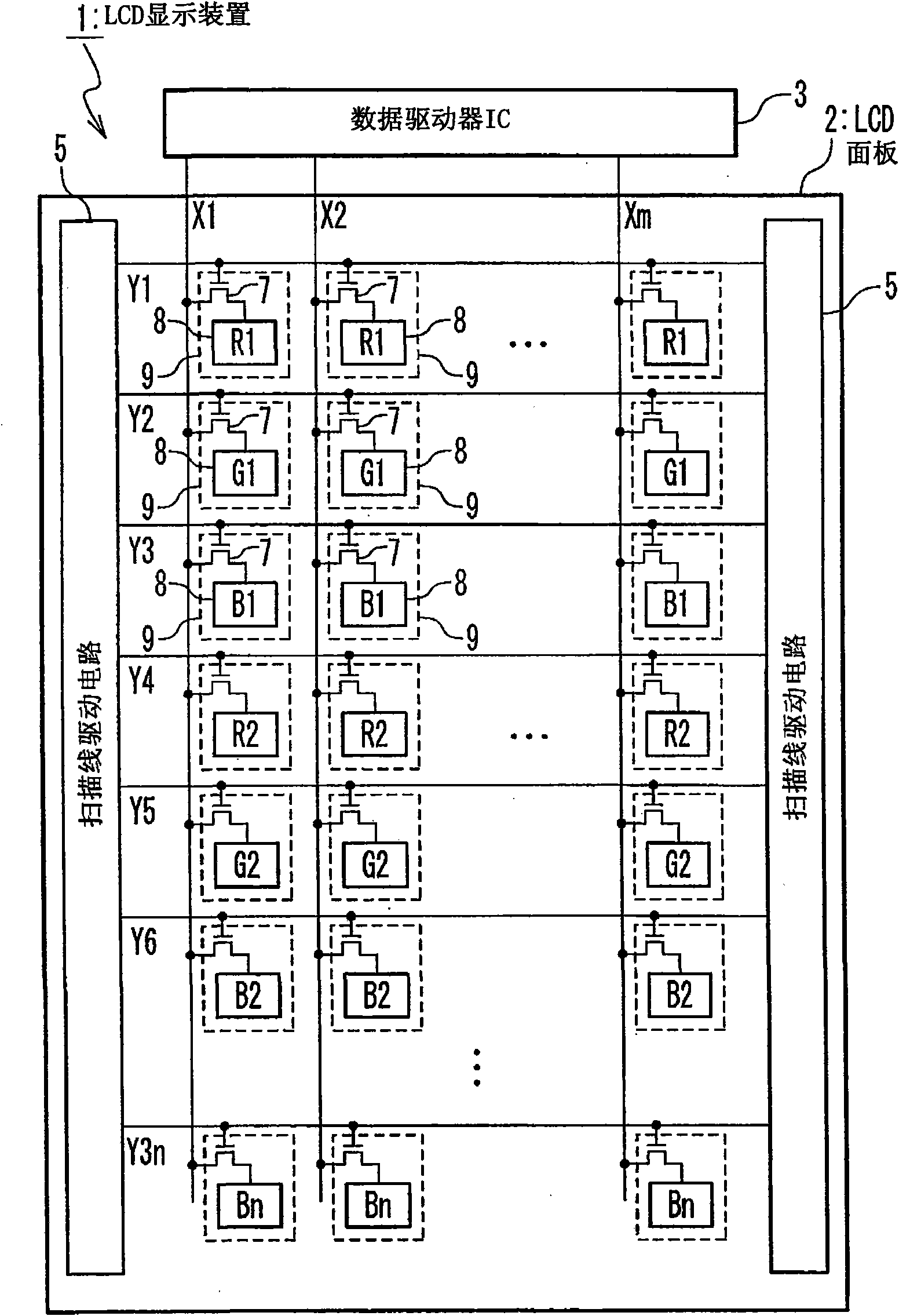
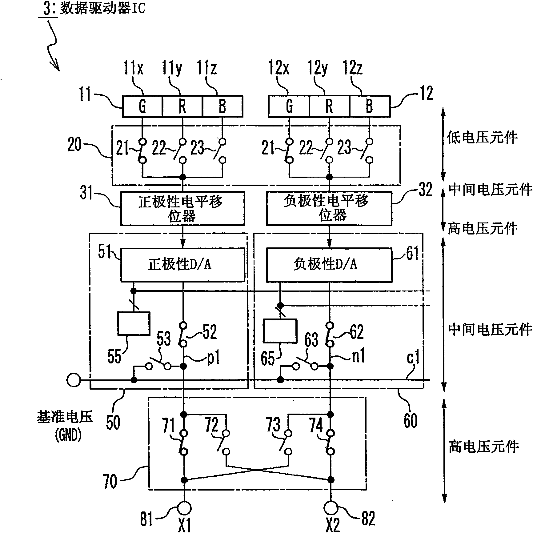
[0034] figure 1 is a block diagram showing the configuration of the liquid crystal display device according to the first embodiment of the present invention. The liquid crystal display device 1 has a liquid crystal display panel 2 and a data driver IC 3 having a built-in timing control circuit. The data driver IC 3 drives the data lines X1 to Xm of the liquid crystal display panel 2 . Also, the data driver IC 3 supplies a control signal to the scanning line driving circuit 5 and supplies a fixed voltage to the common electrode. As the mounting state of the data driver IC 3, there are COG (Chip On Glass), COF (Chip On Film), TCP (Tape Carrier Package), and the like.

[0035]In the liquid crystal display panel 2, data lines X1 to Xm and scanning lines Y1 to Y3n are formed, and a liquid crystal cell 9 is formed at the intersection of these lines to serve as a display unit. The liquid crystal cell 9 is provided with a TFT 7 (Thin Film Transistor) serving as a switching element ...

no. 2 example

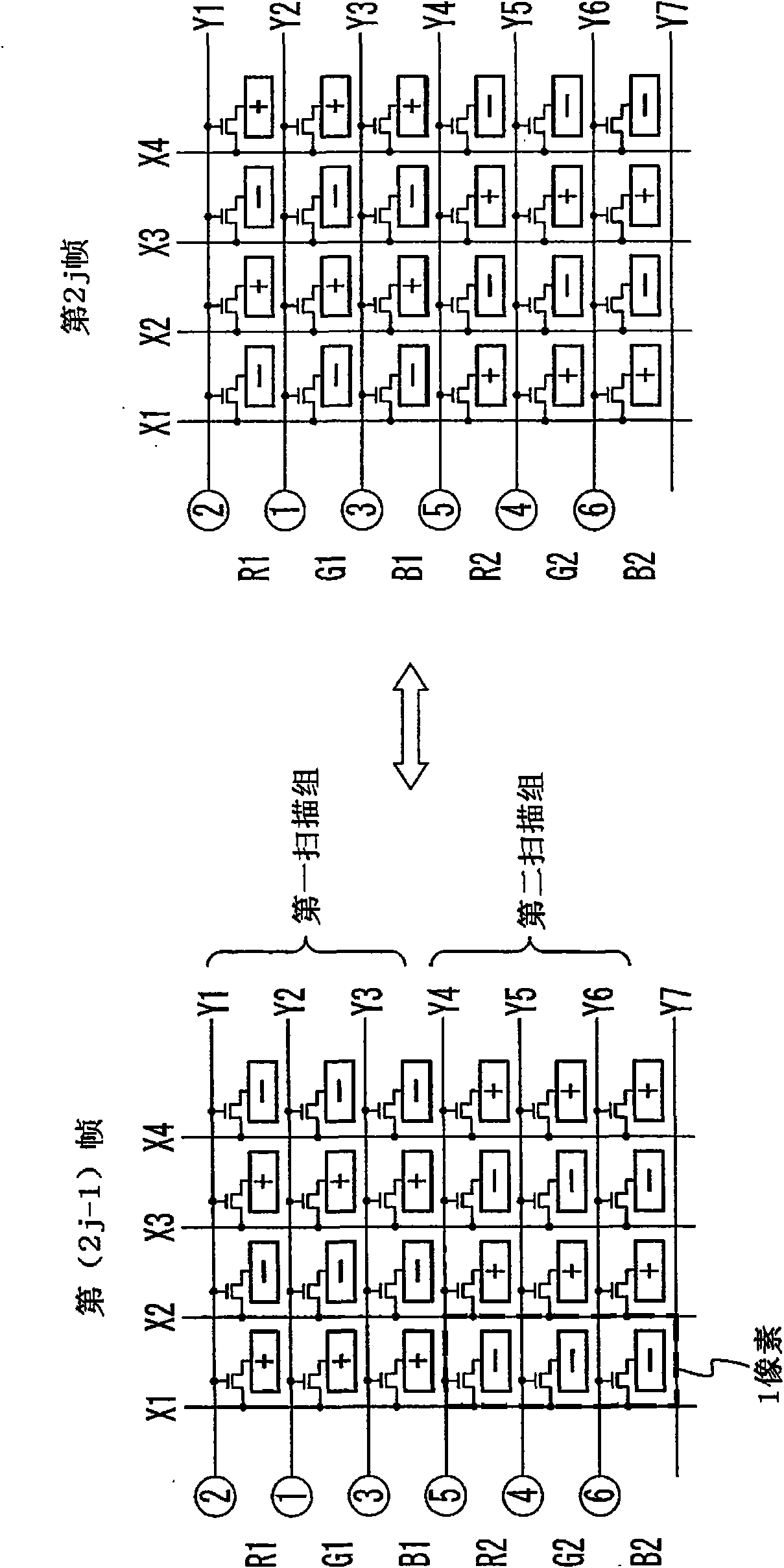
[0097] In the second embodiment, although it is the same as first selecting the scan line corresponding to green (G) in each scan group immediately after the precharge, the scan line corresponding to red (R) is changed every two frame periods The first embodiment of the scan driving sequence of the line and the scan line corresponding to blue (B) is the same. But the selection order of the scan line corresponding to red (R) and the scan line corresponding to blue (B) may be changed every two horizontal periods and every two frame periods.

[0098] Figure 7 is a conceptual diagram showing a method for driving the liquid crystal cell 9 in the second embodiment. In the (4j-3)th frame period and the following (4j-2)th frame period, according to the scan line corresponding to green (G), the scan line corresponding to red (R), and the scan line corresponding to blue The sequence of scan lines of (B) drives the scan lines of each scan group. More specifically, the scanning order ...

no. 3 example

[0105] In the third embodiment, red (R) and blue (B) are prevented from being ) of the pixel electrode in the liquid crystal cell 9 becomes shorter. More specifically, as Figure 8 As shown in , in the period from time t12 to time t13, the scanning period of the scanning line Y2 corresponding to green (G) (the period from time t11 to time t13) and the scanning of the scanning line Y1 corresponding to red (R) The periods (period from time t12 to time t16) overlap. Similarly, the scanning period of the scanning line Y1 corresponding to red (R) (the period from time t12 to time t16) and the scanning period of the scanning line Y3 corresponding to blue (B) in the period from time t15 to time t16 (period from time t15 to time t18) overlap.

[0106] In the first embodiment described above, the drive period TG (period from time t11 to time t14) of the liquid crystal cell 9 for green (G), the drive period TR (period from time t14 to time t17) of the liquid crystal cell 9 for red (R...


PUM


Abstract

A method of driving a display panel is provided. The display panel includes a first scan group including first to third scan lines, and a plurality of data lines which intersect the first to third scan lines, and first display cells of a first color which are connected with the first scan line, second display cells of a second color which are connected with the second scan line, third display cells of a third color which are connected with the third scan line. The method is achieved by precharging the data lines to a predetermined voltage in a first horizontal period; and by supplying a data signal to the first to third display cells through the data lines driving of the first to third display cells after the data lines are precharged in the first horizontal period. In the driving of the first to third display cells, one of the first to third display cells corresponding to one of said first to third colors, having a maximum spectral luminous efficacy, is first driven.

Description

technical field [0001] The present invention relates to a method for driving a display panel, and a display device, and more particularly, to a technique of driving a display panel in which a color array of a display unit is in a horizontal stripe pattern. Background technique [0002] A matrix type liquid crystal display panel in which liquid crystal cells (cells) are arranged in a matrix is ​​one of the most typical display devices. The liquid crystal display panel is provided with liquid crystal cells, scan lines each of which selects a row of liquid crystal cells, and data lines through which data signals are supplied. Liquid crystal cells are arranged at intersections of scan lines and data lines. The liquid crystal cell includes a TFT (Thin Film Transistor) and a pixel electrode, and is filled with liquid crystal between the pixel electrode and a common electrode facing it. [0003] In order to control degradation of the liquid crystal material when driving the liqui...

Claims


Application Information

Patent Timeline
Patent Type & Authority Applications(China)
IPC IPC(8): G09G3/36G09G5/02
Inventor 桥本义春大谷圭吾
Owner NEC ELECTRONICS CORP
Why Eureka
Try Eureka