
Fuse sensor circuit

A technology of induction circuits and fuses, which can be used in information storage, static memory, instruments, etc., can solve problems such as high levels, and achieve the effect of improving sensitivity

Active Publication Date: 2010-01-06
SEMICONDUCTOR MANUFACTURING INTERNATIONAL (BEIJING) CORP
View PDF2 Cites 6 Cited by
  • Summary
  • Abstract
  • Description
  • Claims
  • Application Information

AI Technical Summary

Problems solved by technology

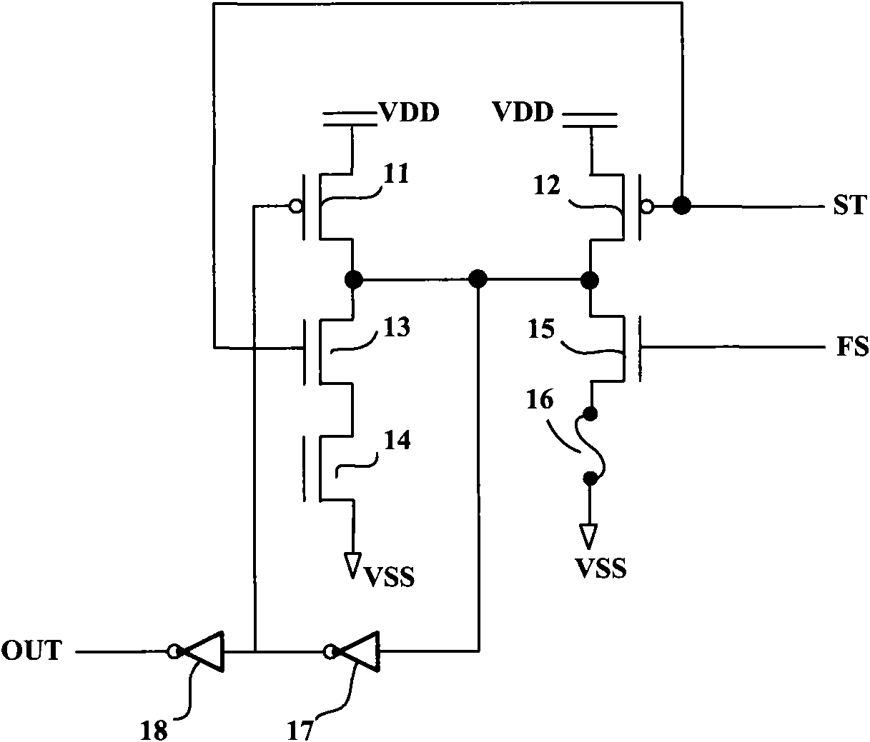
Similar to No. 7,158,435 patent document, in No. 7,183,836 patent document, it is still required to provide a higher programming voltage or programming current to blow the fuse, which is still too high compared to the general working voltage of 2.5-3.3V

Method used


Image

  • Fuse sensor circuit
  • Fuse sensor circuit
  • Fuse sensor circuit

Examples


Embodiment Construction

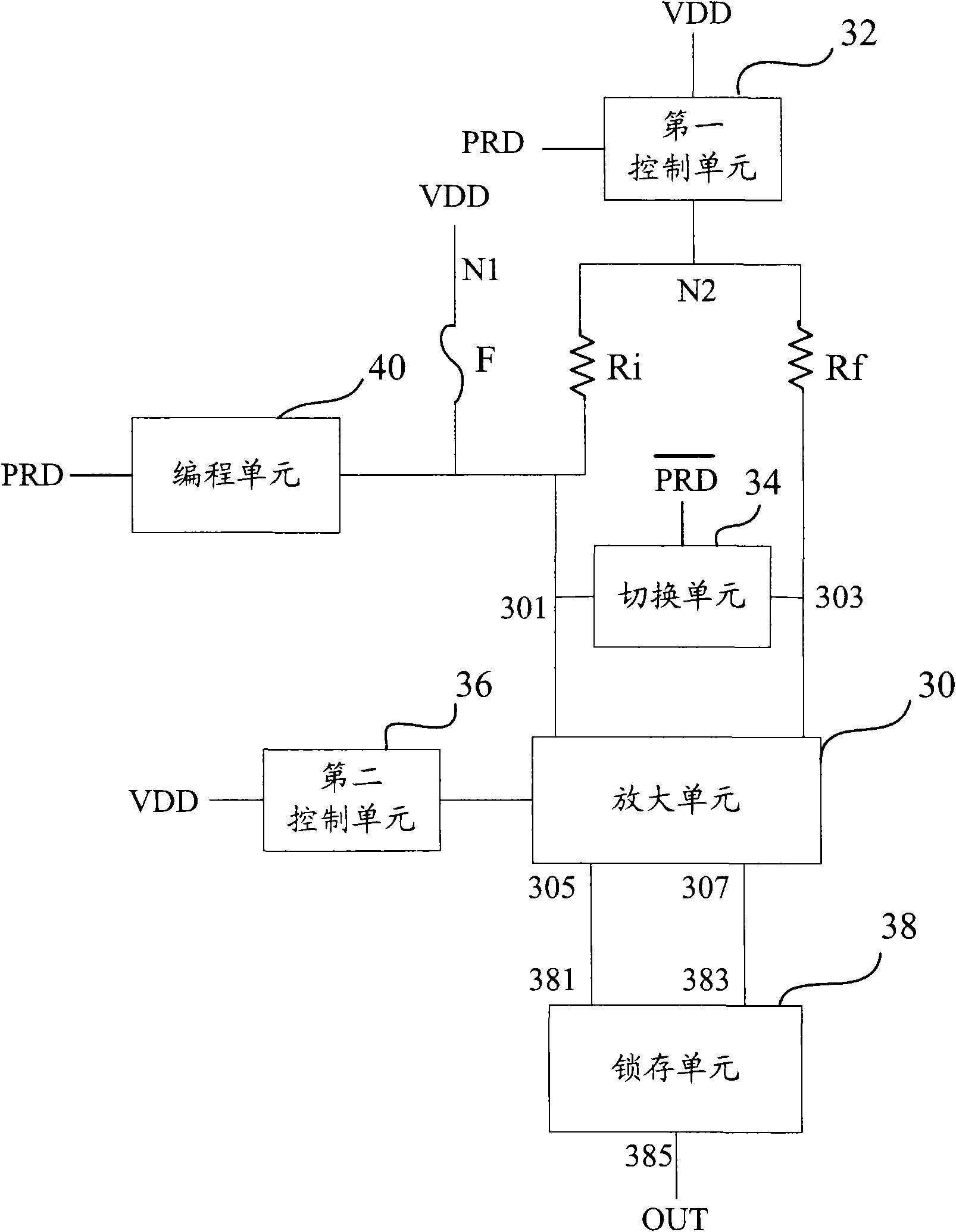
[0033]The embodiment of the present invention provides a shunt resistor that can be connected in parallel with the fuse to act as a shunt during the fuse read operation, so that the amplifying unit can pass through the shunt while ensuring that the current flowing through the fuse is as small as possible. The current of the resistor gets a larger current input, so as to amplify the current and finally output it, thereby improving the sensitivity of the sensing circuit, adapting to a lower programming voltage or programming current, and satisfying the requirement that the programming voltage (current) is still small. detectable fuse state requirements.

[0034] The specific implementation of the present invention will be described in detail below in conjunction with the accompanying drawings and preferred embodiments. image 3 It is a basic circuit block diagram of a fuse sensing circuit according to an embodiment of the present invention. The fuse sensing circuit 3 includes: a...


PUM


Abstract

The invention relates to a fuse sensor circuit, which comprises an amplifying unit, a fuse, a reference resistance, a switch unit, a latch unit and a shunt resistor. The shunt resistor can be connected in parallel with the fuse when the sensor controlling signal controls the opening of the fuse sensor circuit, so that the shunt resistor can bear more current distribution to ensure that the current flowing through the fuse is not too large. Therefore, the amplification unit parallelly superimposes the current in the fuse and the current in the shunt resistor to obtain a large current input to improve the sensitivity of the sensor circuit. The fuse sensor circuit can reduce the strength requirement for the programming voltage or programming current for fuse programming, and is suitable for relatively low programming voltage or programming current.

Description

technical field [0001] The invention relates to a fuse induction circuit. Background technique [0002] Fuses are widely used in analog circuits or digital circuits in semiconductor integrated circuits, and data storage or system settings are performed by blowing fuses. Traditional fuses include metal fuses (Metal Fuse) or polysilicon fuses (Polysilicon Fuse) that are blown by high currents, and metal fuses (Laser Fuse) that are blown by lasers. Now, a new type of electrically programmable fuse (Electrically-Programmable Fuse, e-fuse) that can be realized by electromigration is provided. Typically, programming is accomplished by blowing a fuse by providing a higher programming voltage or programming current in the programming circuit. A fuse is usually considered an open circuit. In fact, after a fuse is blown, it is not really an open circuit, but is considered an open circuit because of its very large resistance. The state of the fuse (unprogrammed or programmed) can be...

Claims


Application Information

Patent Timeline
Patent Type & Authority Applications(China)
IPC IPC(8): G11C17/16
Inventor 杨家奇滕显慧黄强李智高立群
Owner SEMICONDUCTOR MANUFACTURING INTERNATIONAL (BEIJING) CORP
Learn More