Vacuum switch and vacuum switchgear

A vacuum switch and equipment technology, which is applied to electric switches, high-voltage/high-current switches, high-voltage air circuit breakers, etc., can solve the problems of insulation damage and inability to cover insulation cylinders, etc., and achieve the effect of higher insulation reliability

Inactive Publication Date: 2010-01-06
HITACHI IND EQUIP SYST CO LTD
View PDF1 Cites 20 Cited by
  • Summary
  • Abstract
  • Description
  • Claims
  • Application Information

AI Technical Summary

Problems solved by technology

[0007] However, in the structure disclosed in Patent Document 1, although a ring-shaped electric field relaxation shield is arranged at the end of the insulating cylinder, since the two ends of a helical spring are connected in a ring shape, it cann

Method used


Image

  • Vacuum switch and vacuum switchgear
  • Vacuum switch and vacuum switchgear
  • Vacuum switch and vacuum switchgear

Examples


Example Embodiment

[0033] use Figure 1 ~ Figure 5 The first embodiment of the vacuum switch of the present invention will be described.

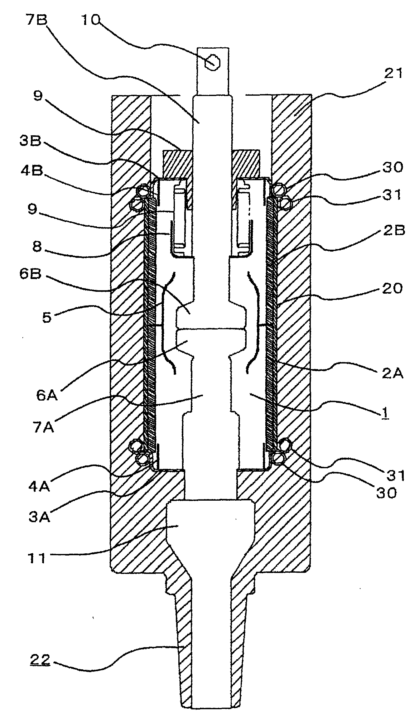
[0034] Such as figure 1 As shown, the vacuum switch 1 of this embodiment roughly includes: a vacuum container 2; fixed and movable electrodes 6A and 6B arranged in the vacuum container 2; and a solid insulating resin 21 covering the periphery of the vacuum container 2.

[0035] The vacuum vessel 2 includes: a fixed-side ceramic insulating cylinder 2A; a movable-side ceramic insulating cylinder 2B connected to the fixed-side ceramic insulating cylinder 2A; connected to the axial fixed side end of the fixed-side ceramic insulating cylinder 2A and having a thickness greater than that of the insulating cylinder 2A, 2B thin metal fixed-side end plate 3A; and metal movable-side end plate 3B connected to the axially movable side of the movable-side ceramic insulating cylinder 2B, and the inside is maintained in a high vacuum state. The joint surfaces of the two insulatin...


PUM


Abstract

The present invention relates to a vacuum switch and a vacuum switchgear. The object of the invention is to provides a vacuum switch covered by solid insulation resin with high insulation performance. The vacuum switch comprises a fixed electrode, a movable electrode facing the fixed electrode, an insulating cylinder, end plates covering both axial ends of the insulating cylinder, a vacuum chamber internally accommodating the fixed electrode and the movable electrode, and a solid isolation resin molded on the outside of the vacuum chamber, characterized in that, a first coil springs, each of which is disposed around the outer circumference of one end plate while touching the end plate and an end face of the insulating cylinder, and a second coil springs, each of which is united to one of the first springs and disposed around the outer circumference of the insulating cylinder so as to cover the angular part of the end face of the insulating cylinder, and the end plates, the end faces of the insulating cylinder, and the first and second coil springs are electrically connected.

Description

technical field [0001] The present invention relates to a vacuum switch and a vacuum switchgear, and more particularly, to a vacuum switch and a vacuum insulated switchgear suitable for insulatingly molding the periphery of a vacuum container accommodating a switch portion. Background technique [0002] A vacuum switch is a switch with high insulation performance utilizing a vacuum, and can be miniaturized and gas-free. [0003] In a vacuum switch, there is not only a vacuum insulation, but also a structure in which the insulation performance is enhanced by covering the periphery of the switch vessel with a solid insulating resin to form a double insulation structure. [0004] However, when the periphery of the switch vessel of the vacuum switch is covered with a solid insulating resin, an electric field is concentrated at the end of the insulating cylinder constituting the switch vessel, and dielectric breakdown is likely to occur. [0005] Then, there is a structure descr...

Claims


Application Information

Patent Timeline
IPC IPC(8): H01H33/66
CPCH01H2033/66215
Inventor 土屋贤治佐藤隆山崎美稀小林将人小泽裕之
Owner HITACHI IND EQUIP SYST CO LTD
Why Eureka
Try Eureka