Moving-magnetic type linear motor

A linear motor and moving magnet technology, applied in the direction of magnetic circuit shape/style/structure, electromechanical devices, electrical components, etc., can solve the difficulty of increasing yoke processing, installation and maintenance, lack of simple and effective methods, and is not conducive to Solve problems such as armature heat dissipation, achieve easy processing, improve the utilization rate of permanent magnets, and improve the effect of heat dissipation

Inactive Publication Date: 2010-01-06
HUAZHONG UNIV OF SCI & TECH
View PDF0 Cites 13 Cited by
  • Summary
  • Abstract
  • Description
  • Claims
  • Application Information

AI Technical Summary

Problems solved by technology

In terms of electromagnetic structure, the motor with this structure often arranges permanent magnet rings with different polarities next to each other, such as figure 1 The permanent magnets 41 and 42 are adjacent to each other, and the permanent magnets 43 and 44 are adjacent to each other, so that a considerable part of the permanent magnet flux is directly closed without passing through the armature core, which increases the leakage loss and reduces the performance of the permanent magnet; The coil 2 is in the semi-enclosed yoke iron box 1, which increases the difficulty of processing, installation and maintenance of the yoke iron; and is not conducive to the heat dissipation of the armature; when changing the electromagnetic power according to the application requirements, there is a lack of simple and effective methods

Method used


Image

  • Moving-magnetic type linear motor
  • Moving-magnetic type linear motor
  • Moving-magnetic type linear motor

Examples


Embodiment Construction

[0027] The present invention will be described in further detail below in conjunction with accompanying drawing and example.

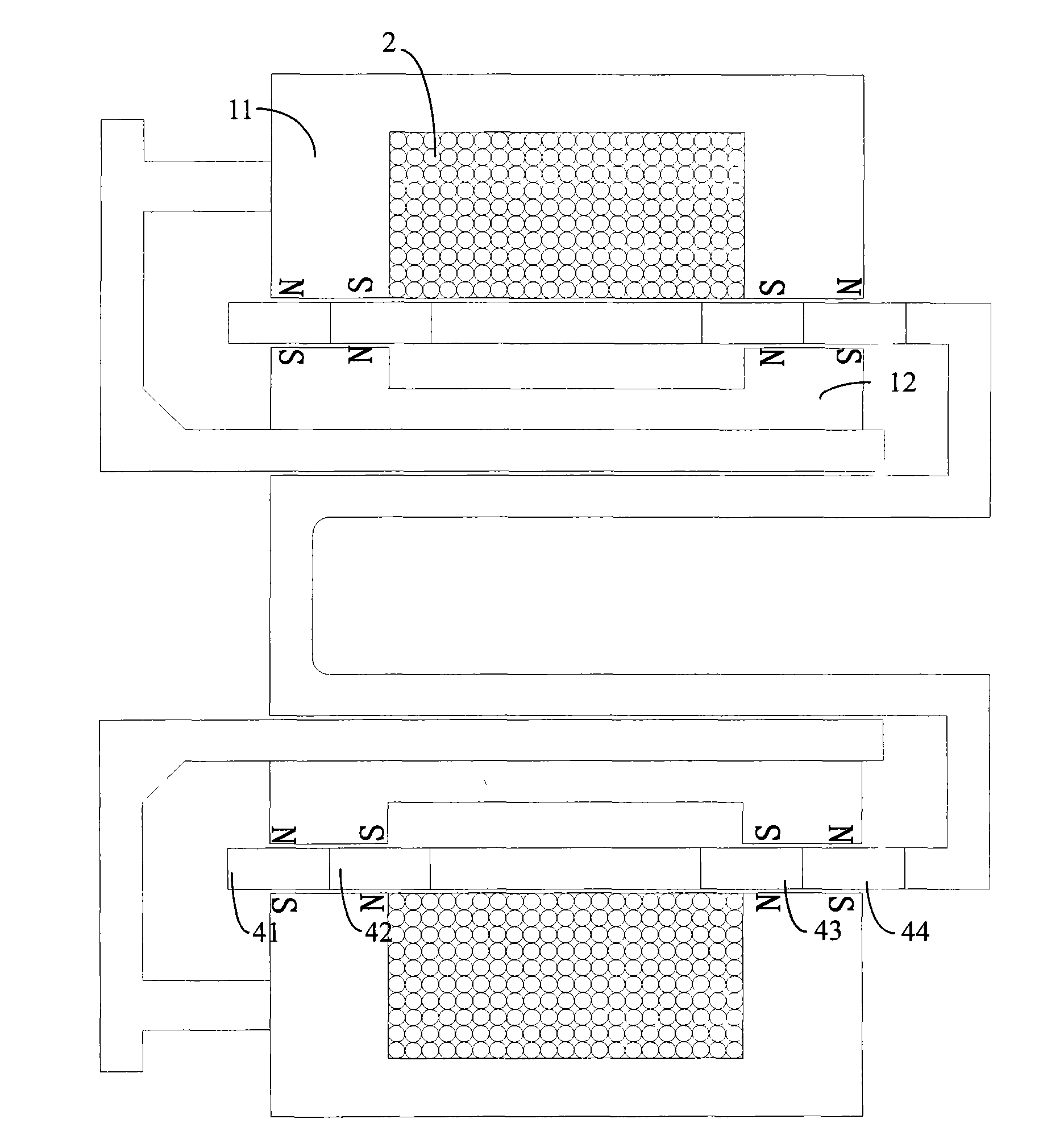
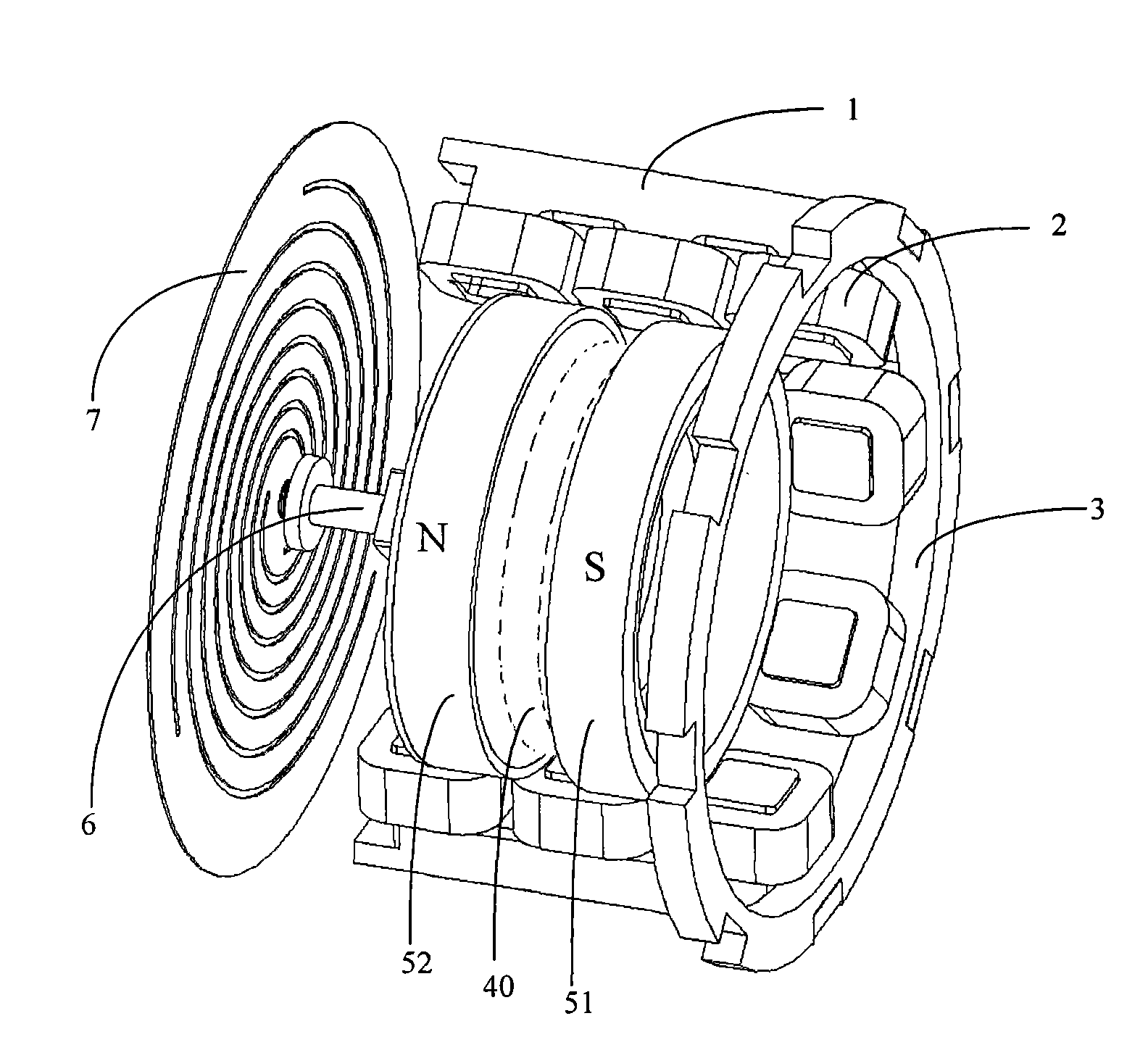
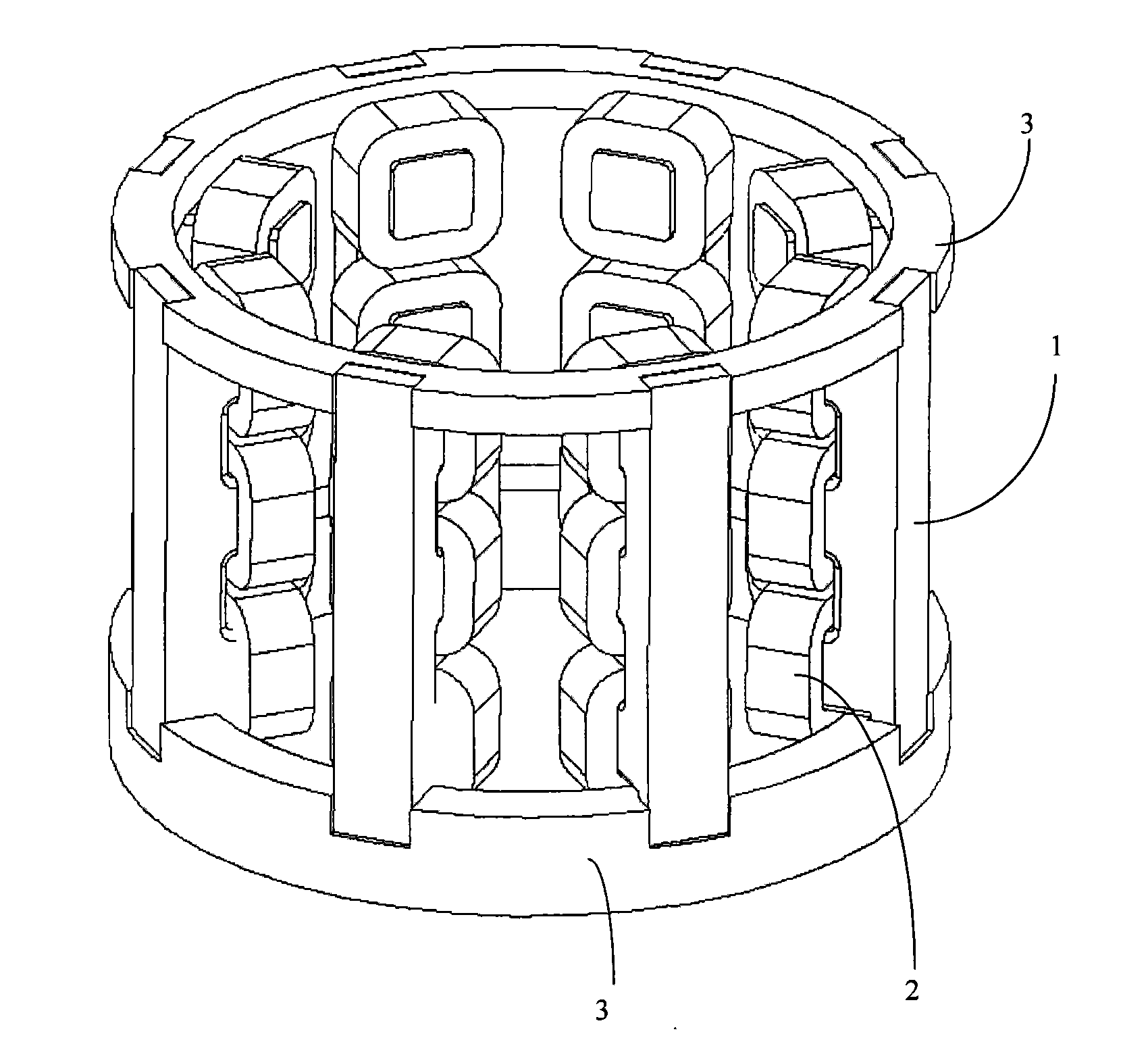
[0028] The present invention includes a casing 10 and a stator and a mover inside it. Such as figure 2 and image 3 As shown, the stator includes two ring-shaped yoke support rings 3, and eight strip-shaped stator yokes 1 evenly distributed along the ring are arranged between the two yoke support rings. The inner surface of the stator yoke 1 is Alveolar structure, the alveolar structure includes three stator teeth 102, and two stator slots 103 are formed between adjacent stator teeth. Stator coils 2 are placed on the slot structure, and after the stator coils 2 are energized, the magnetic poles of adjacent stator teeth are opposite. refer to Figure 4 and 5 , both ends of the stator yoke 1 have boss structures 101, and the yoke support ring 3 is evenly distributed with groove structures 301 along the outer circumferential direction, through the c...


PUM


Abstract

The invention provides a moving-magnetic type linear motor which mainly comprises a stator and a rotor, wherein the stator comprises two yoke supporting rings in the shape of a circular ring, and at least four strip-shaped stator yokes which are uniformly distributed along the circular ring are arranged between the two yoke supporting rings; the inner surface of each stator yoke is in a tooth socket structure which comprises N stator teeth; a coil is coiled on the tooth socket structure; after the coil is electrified, adjacent stator teeth form opposite magnetic poles; the rotor is positioned in a cylindrical cavity surrounded by the stator yokes; for each stator yoke, the rotor has N-1 magnetic poles which are axially arranged in parallel, the magnetic lines of the magnetic poles are distributed in the radial direction, and the polarities of adjacent magnetic poles which are arranged at intervals are opposite; and the rotor is connected with a plate spring through a connection shaft. The moving-magnetic type linear motor reduces the magnetic leakage loss, improves the permanent magnet efficacy, has good radiating effect and simple and compact structure, and is convenient in installation and maintenance.

Description

technical field [0001] The invention belongs to the technical field of motors, in particular to a moving magnet linear motor. Background technique [0002] Traditional moving magnet linear oscillating motors such as figure 1 As shown, it has a cylindrical axisymmetric outer iron yoke 11 and an inner iron yoke 12 , and the armature coil 2 is embedded in the groove of the outer iron yoke 11 . Four permanent magnetic rings 41, 42, 43, 44 are located in the air gaps of the inner and outer iron yokes. When the permanent magnet mover moves from the position shown in the figure to the right end of the stroke, the main magnetic flux passes through the inner and outer iron yokes 11, 12 and the permanent magnets 41 and 43 to form a loop, and the permanent magnet flux is clockwise; when the permanent magnet mover moves from When the position shown in the figure moves to the left end of the stroke, the main magnetic flux passes through the inner and outer iron yokes 11, 12 and the per...

Claims


Application Information

Patent Timeline
Patent Type & Authority Applications(China)
IPC IPC(8): H02K41/02H02K1/12H02K1/27
Inventor 张晓青李奎
Owner HUAZHONG UNIV OF SCI & TECH
Why Eureka
Try Eureka