
Method for splicing large-scale video with separated dynamic foreground

A technology of foreground separation and video splicing, applied in the field of video splicing and panoramic video, it can solve the problems of blind spots, poor definition, and high cost.

Inactive Publication Date: 2010-01-06
BEIJING UNIV OF TECH
View PDF0 Cites 64 Cited by
  • Summary
  • Abstract
  • Description
  • Claims
  • Application Information

AI Technical Summary

Problems solved by technology

The video monitoring of 360° space can be realized through the high-speed movement of the fast ball, but the system can only monitor the picture at a certain angle at a certain moment, and blind spots will inevitably appear during monitoring; the second is to use the fisheye lens The wide angle of view directly obtains the 360° scene, and the panoramic video is obtained after transformation. The panoramic video generated by this method has low resolution and poor definition; the third method is to use a secondary convex mirror and a camera combination to shoot The emission image transformation on the convex mirror generates a panoramic video. This method requires expensive professional video acquisition equipment, and the panorama is obtained by transforming one image, which cannot meet the high-resolution requirements. In addition, some research institutions use the camera to Certain geometric constraints are fixed to form a camera group, which achieves a video spherical splicing system, but this kind of system has strict requirements on the geometric position of the cameras, and the production process is meticulous, so it is not suitable for general applications, and at the same time, it cannot solve the ghost image that appears in the splicing Phenomenon

Method used


Image

  • Method for splicing large-scale video with separated dynamic foreground
  • Method for splicing large-scale video with separated dynamic foreground
  • Method for splicing large-scale video with separated dynamic foreground

Examples


Embodiment Construction

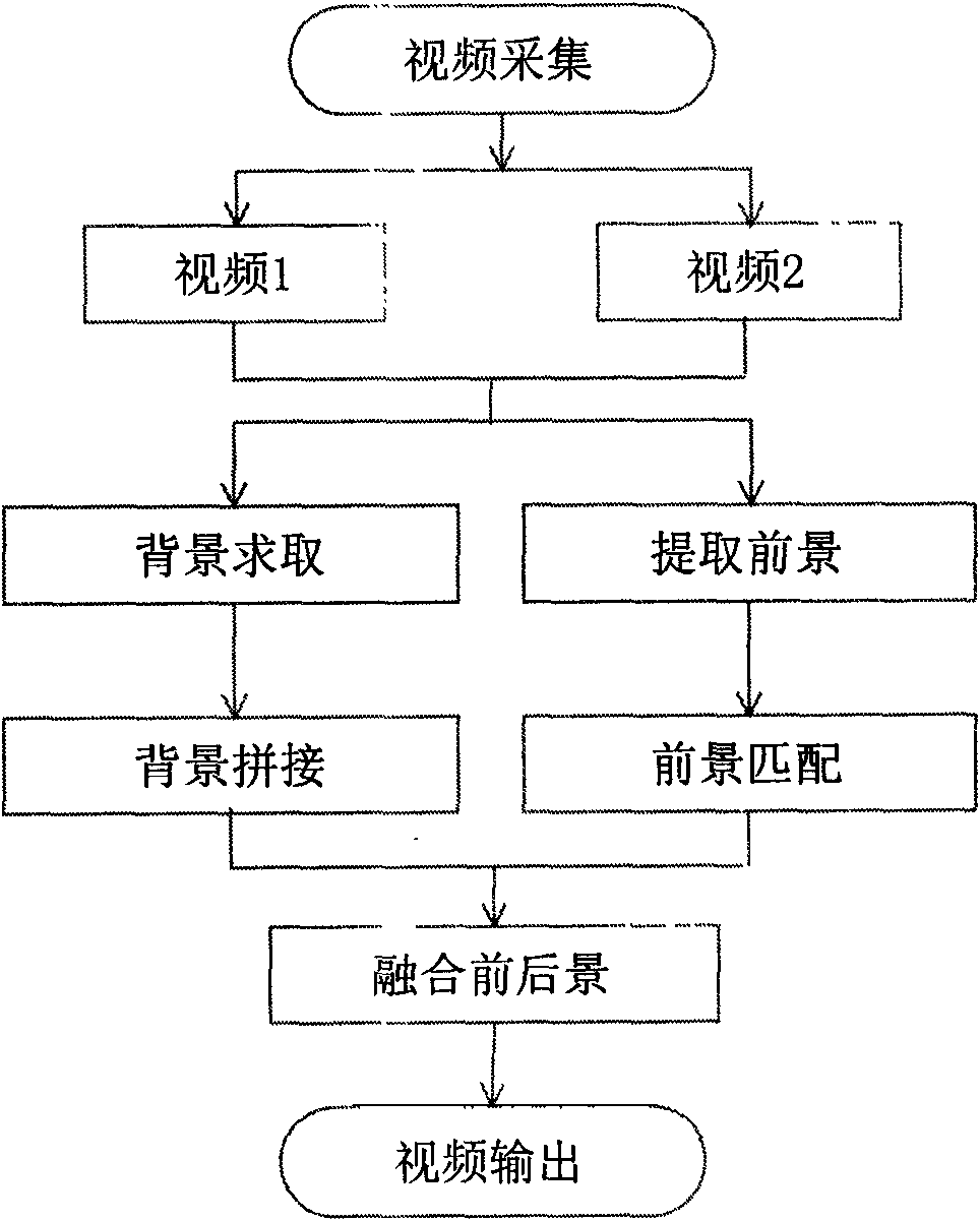
[0064] In the large-format video splicing method with dynamic foreground separation provided by the present invention, the number of cameras used may be 2 or more. In this embodiment two identical cameras are used. The position of the camera can be adjusted according to the shooting environment. The distance between the optical centers of the cameras is adjusted by the distance of the shooting scene. The closer the scene is to the camera, the smaller the distance between the cameras is required; for indoor shooting, the distance between the optical centers of the cameras is 5-10cm; For outdoor shooting, the optical center distance of the cameras is 5-100cm, and the overlapping area of ​​the shooting areas of adjacent cameras is 20%-50%. In this embodiment, the shooting is done indoors, the distance between the optical centers of the cameras is 5 cm, and the overlapping area of ​​the videos taken by the two cameras is about 25%. The specific placement is as Figure 5 shown. ...


PUM


Abstract

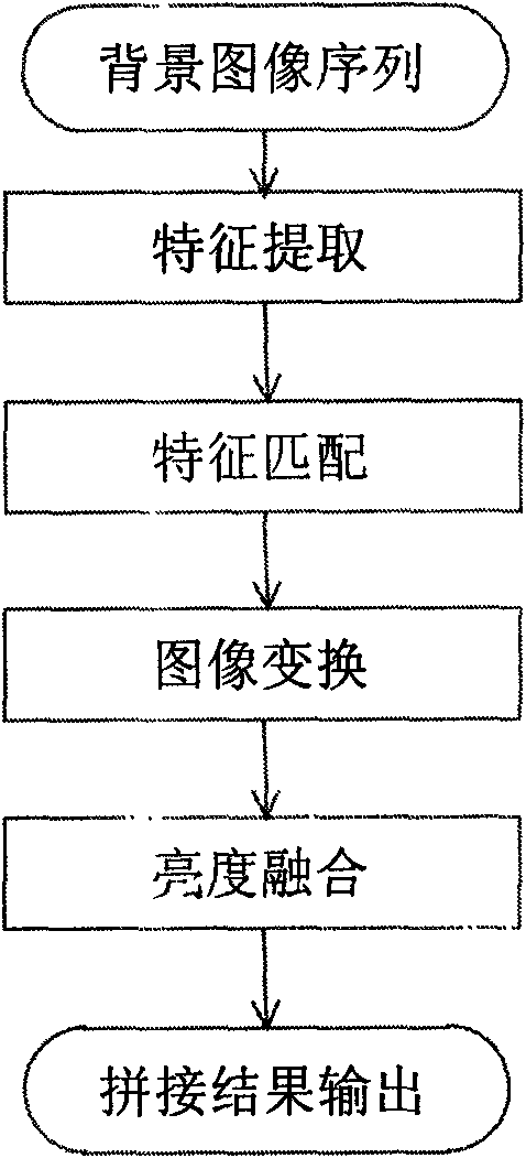
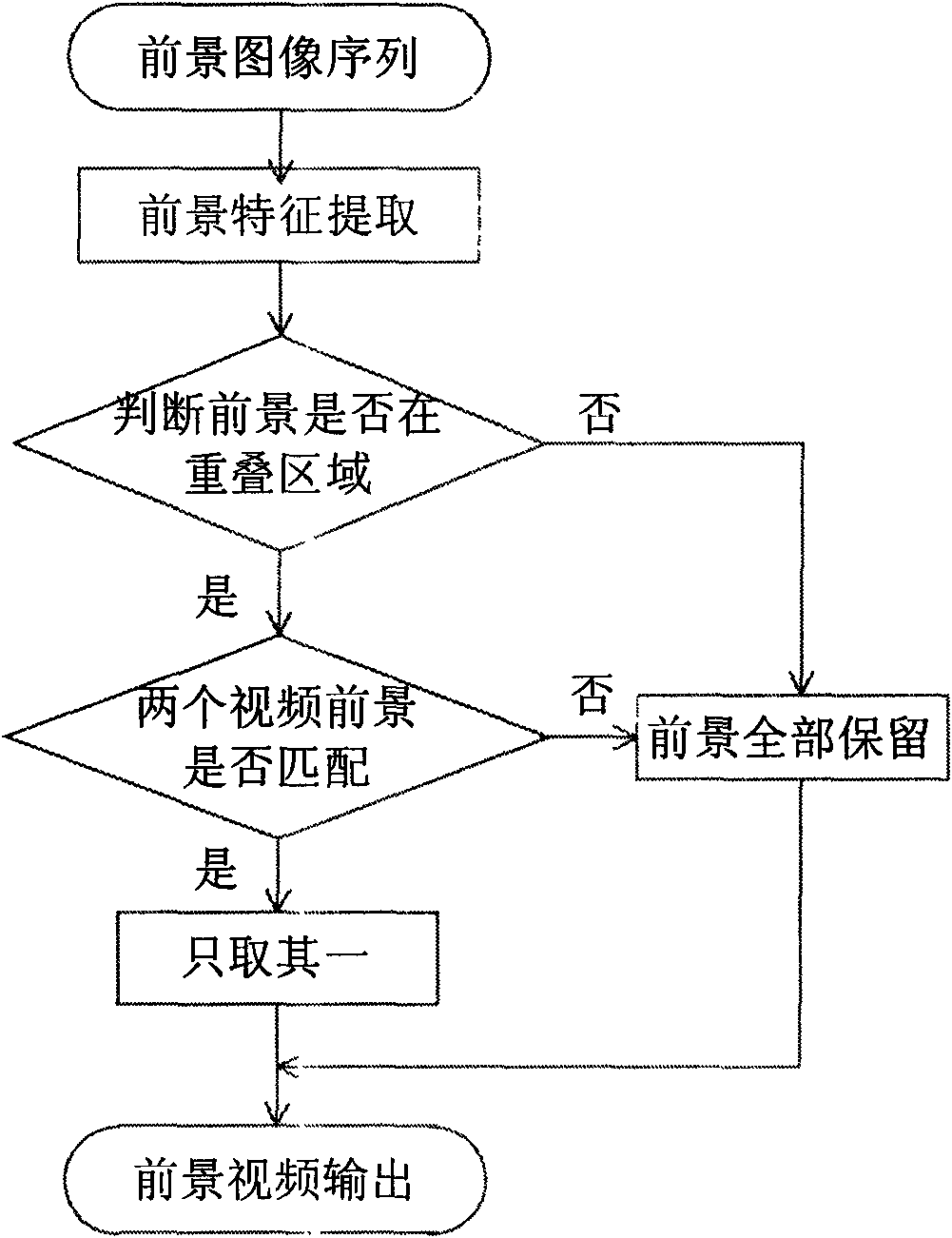
The invention discloses a method for splicing large-scale video with a separated dynamic foreground, which relates to the field of video splicing and panorama video. The method comprises the following steps: shooting by cameras with multiple positions and relatively fixed and same shooting angles to obtain video data, sequentially reading video sequences by a computer system, sequentially carrying out geometry correction and foreground extraction on the video sequences, then respectively matching and exchanging foreground video sequences and background video sequences to obtain spliced foreground and background video, and finally syncretizing the spliced foreground and background video to obtain a final video splicing result. The placing position of the cameras used in the invention can be adjusted according to the shooting environments, and the number of the cameras can be 2 or more. The method avoids generating a ghost shadow through separating the foreground and reselecting data to be remained by one part in an overlapped region. Tests prove that the method not only ensures the video quality, but also increases the speed of a splicing algorithm.

Description

technical field [0001] The invention relates to the fields of video splicing and panoramic video, and designs and implements a video splicing method based on multi-camera foreground separation. Background technique [0002] With the continuous development of information technology, people's requirements for video information collected by cameras are also constantly increasing. Panoramic video splicing technology breaks through the physical limitations of camera acquisition sensors. By splicing video streams shot by multiple cameras at the same time, high-resolution panoramic videos can be obtained, which can greatly improve people's dynamic perception, identification, and monitoring capabilities for things and scenes. fields, especially security, military, national defense and other fields to reduce risks and improve safety; panoramic video stitching technology is also used in industrial fields such as vehicle rearview mirrors; in video post-editing and production, panoramic...

Claims


Application Information

Patent Timeline
Patent Type & Authority Applications(China)
IPC IPC(8): H04N5/262G06T5/00
Inventor 贾克斌张媛
Owner BEIJING UNIV OF TECH
Learn More