
Optical cable

A technology of optical cable and optical fiber core, applied in the direction of fiber mechanical structure, etc., can solve the problem of increased transmission loss, and achieve the effect of suppressing rupture, excellent impact resistance, and reducing damage

Active Publication Date: 2010-01-06
SUMITOMO ELECTRIC IND LTD
View PDF2 Cites 9 Cited by
  • Summary
  • Abstract
  • Description
  • Claims
  • Application Information

AI Technical Summary

Problems solved by technology

However, compared with general-purpose single-mode optical fibers, multimode optical fibers are prone to increase transmission loss due to external interference factors such as temperature expansion and contraction.

Method used


Image

  • Optical cable
  • Optical cable
  • Optical cable

Examples


no. 1 example

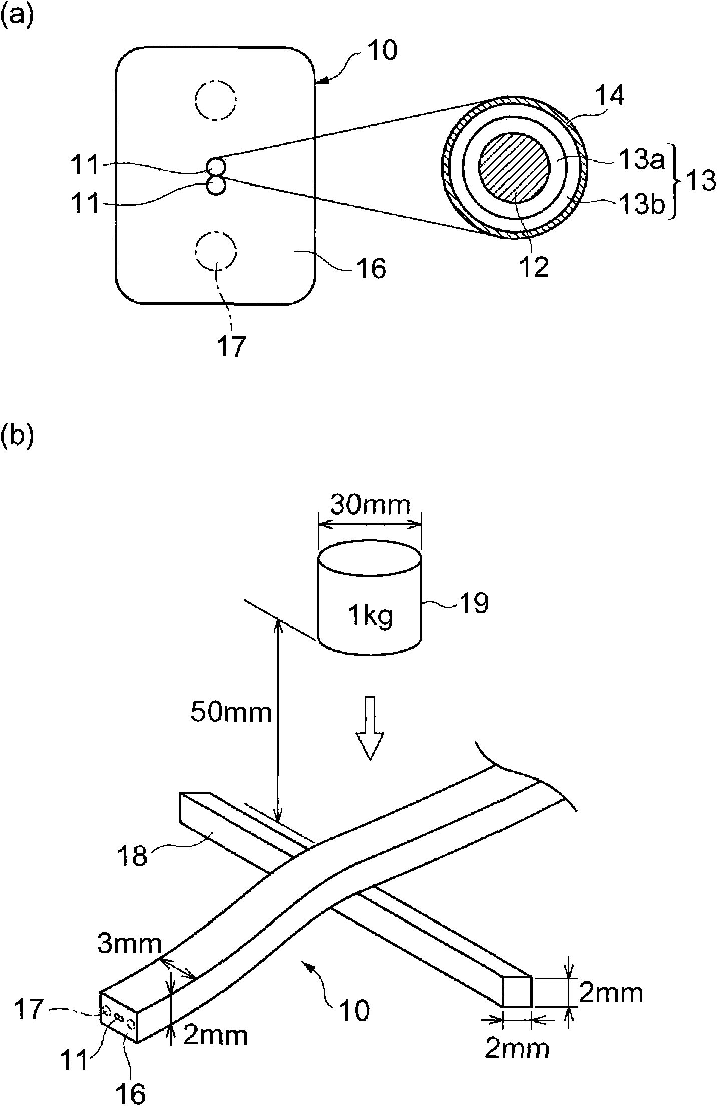
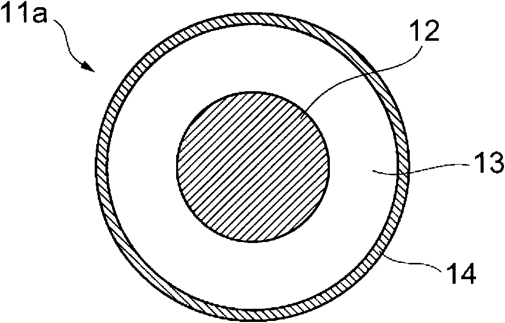
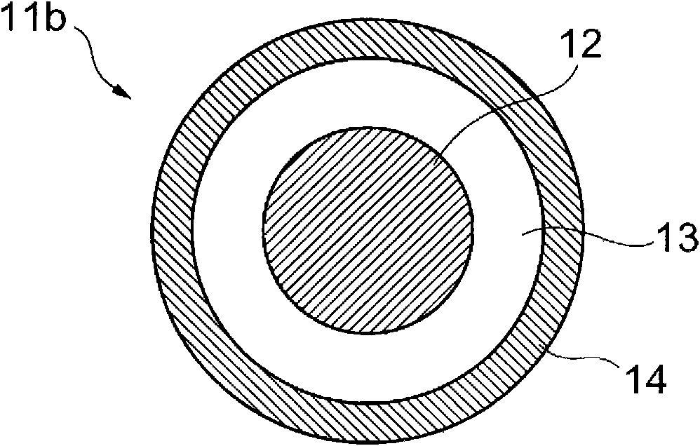
[0055] First, refer to Figure 1 to Figure 7 A first embodiment of the optical cable according to the present invention will be described in detail. figure 1 is a diagram for explaining the first embodiment of the optical cable of the present invention, in particular, the area (a) shows the basic structure (cross-sectional structure) of the optical cable, and the diagram of the area (b) shows the impact resistance of the optical cable for explaining sex test method. exist figure 1 In the region (a), the optical cable 10 is equipped with an optical fiber core wire 11, a tension member 17 arranged on both sides of the optical fiber core wire 11 along the optical fiber core wire 11, and the optical fiber core wire 11 and the tension member 17 are covered in one body The cable sheath 16. The optical fiber core 11 includes a bare fiber (glass fiber) 12 , a cladding 13 provided on the outer periphery of the glass fiber 12 , and a colored layer 14 provided on the surface of the ...

no. 2 example

[0110] Below, will refer to Figures 8 to 13 A second embodiment of the optical cable according to the present invention will be described in detail. Figure 8 is a diagram showing the basic structure (cross-sectional structure) and appearance of the second embodiment of the optical cable according to the present invention. In particular, the region (a) represents the first cross-sectional structure (rectangular shape) of the optical cable 20 according to the second embodiment, the region (b) represents the second cross-sectional structure (elliptical shape) of the optical cable 20 according to the second embodiment, and the region (c) shows an example of a LAN optical cable using the optical cable 20 (in a state where an optical connector is attached). The optical cable 20 according to the second embodiment is the same as the first embodiment, and also has an optical fiber core wire 11, a tension member 17 arranged on both sides of the optical fiber core wire 11 along the op...


PUM

PropertyMeasurementUnit
Young's modulusaaaaaaaaaa

Abstract

The invention relates to an optical cable having a structure for improving durability. The optical cable is provided with an optical fiber core wire and a cable jacket covering the outer circumference of the optical fiber core wire. The optical fiber core wire is composed of a glass fiber, and a coat layer composed of an ultraviolet curing resin. To have excellent shock resistance as durability characteristics, the coat layer of the optical fiber core wire includes a first coat having a Young's modulus of 200Mpa or more. The cable jacket is composed of a thermal plastic resin not containing halogen. The cable jacket is composed of the thermal plastic resin not containing halogen. The cable jacket has a thickness of 0.7mm or more, a frame resistance of V2 or more in UL standards, and a Young's modulus equivalent to that of the first coat or higher.

Description

technical field [0001] The present invention relates to an optical cable applicable to optical LAN wiring for connection between information devices and the like. Background technique [0002] With the advancement of optical communication technology in recent years, LAN (Local Area Network) wiring for optical communication and wiring between devices have begun to be used. If the use in intricate parts or special environments with bumps is also considered, it is expected that optical cables used in optical LAN wiring indoors or in vehicles, optical wiring between equipment, etc. are excellent in flexibility. and thin-diameter optical cables. [0003] Optical cables used in the above-mentioned special environments are shorter in size (1m to 20m) than ordinary optical cables (optical cables for long-distance communication). Therefore, such a short-sized optical fiber cable does not require low transmission loss like ordinary optical fiber cables. On the contrary, when the op...

Claims


Application Information

Patent Timeline
IPC IPC(8): G02B6/44
Inventor 坂部至屉冈英资服部知之
Owner SUMITOMO ELECTRIC IND LTD
Features
  • Generate Ideas
  • Intellectual Property
  • Life Sciences
  • Materials
  • Tech Scout
  • Unparalleled Data Quality
  • Higher Quality Content
  • 60% Fewer Hallucinations
Learn More