Eureka AIR delivers breakthrough ideas for toughest innovation challenges, trusted by R&D personnel around the world.

Permanent magnet synchronous motor

A permanent magnet synchronous motor technology, applied to synchronous motors with stationary armatures and rotating magnets, synchronous machine parts, electric components, etc., can solve problems such as rotor temperature rise, improve power factor, and reduce eddy current heating , The effect of reducing the risk of demagnetization

Inactive Publication Date: 2010-01-13
NANTONG JINCHI MECHANICAL ELECTRIC
View PDF3 Cites 10 Cited by
  • Summary
  • Abstract
  • Description
  • Claims
  • Application Information

AI Technical Summary

Problems solved by technology

[0008] In order to fundamentally solve the problem of excessive temperature rise of the rotor in the use of permanent magnet synchronous motors and ensure its service life, the present invention provides a permanent magnet synchronous motor, which adopts a new external circulation ventilation cooling structure from the rotor to enhance the ventilation and cooling of the rotor Effect: strengthen the permanent magnet insulation layer, reduce eddy current heating, and improve the service life of the motor

Method used


Image

  • Permanent magnet synchronous motor
  • Permanent magnet synchronous motor
  • Permanent magnet synchronous motor

Examples


Embodiment Construction

[0035] The present invention will be further described below in conjunction with drawings and embodiments.

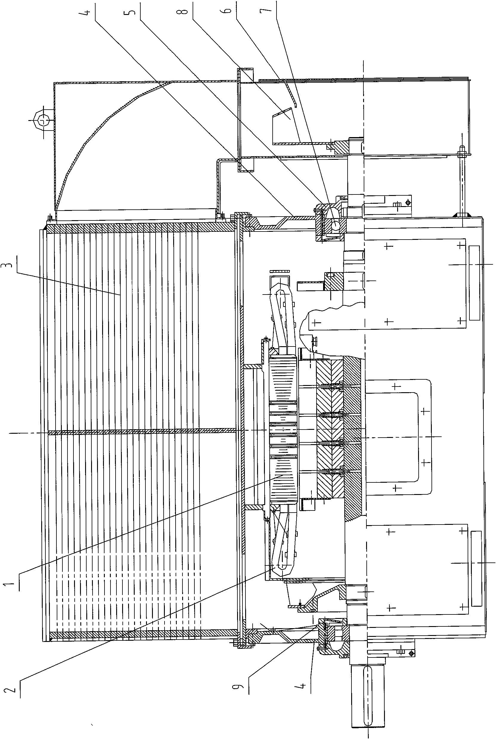
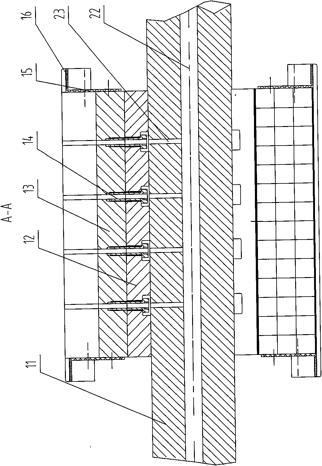
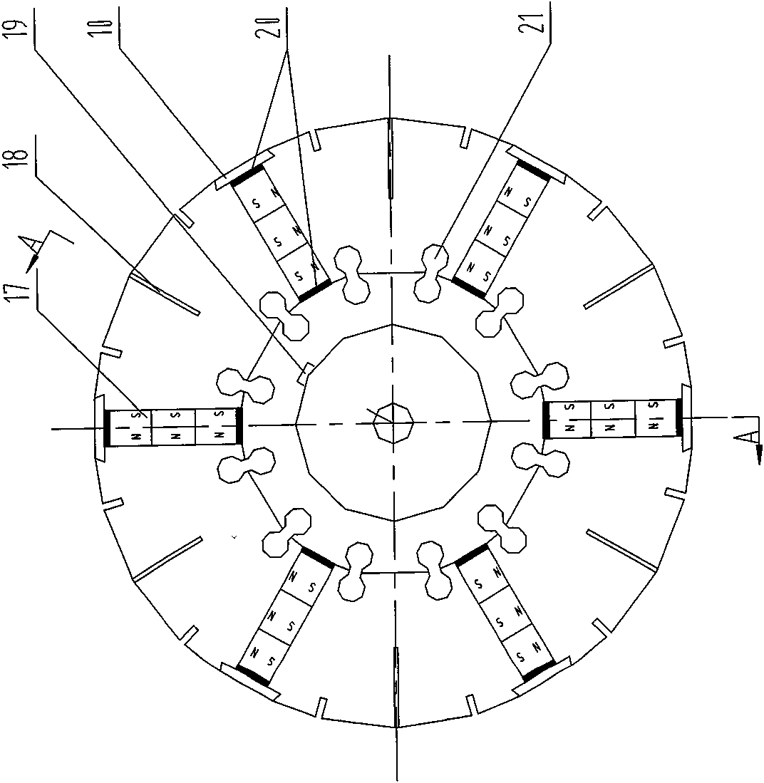
[0036] exist figure 1 Among them, the permanent magnet synchronous motor consists of two major components: the stator and the rotor. The stator part consists of a casing, a stator core 1 and an armature winding 2. The casing is composed of a casing 3, an end cover 4, a bearing cover 5 and a protective cover 6, and its structure is basically the same as that of an ordinary three-phase asynchronous motor. The stator of an ordinary three-phase asynchronous motor can be directly matched with the rotor part of the present invention to form a permanent magnet synchronous motor, which is a major feature of the present invention; another major feature of the present invention is that the structure of the rotor part is changed. figure 2 and image 3 Among them, the hollow core shaft 11, the magnetic isolation sleeve 12, and the split magnetic pole 13 are coaxially assembled ...


PUM


Abstract

The invention discloses a permanent magnet synchronous motor consisting of a stator component and a rotor component. The stator component consists of a casing, a stator iron core and a armature winding, wherein a rotor shaft is a hollow shaft, and an internal ventilation hole with two communicated ends are arranged inside the hollow shaft; the rotor shaft is provided with an external ventilation hole communicated with the internal air through hole in the hollow shaft along a radial direction of the rotor shaft; a magnetic shield is provided with a ventilation hole of the magnetic shield along the radial direction; a magnetic pole is provided with a ventilation hole of the magnetic pole along the radial direction; the ventilation hole of the magnetic shield and the ventilation hole of the magnetic pole are communicated with the internal ventilation hole, and the three ventilation holes form a radiant-type radiating structure with the axial direction crossed with the radial direction. Compared with the prior art, the invention excellently controls the temperature rise of the motor in operation, reduces the demagnetization danger of an Nd-Fe-B permanent magnet, and reduces vortex heating and prolongs the service life of the normal operation of the motor at the same time.

Description

technical field [0001] The invention relates to the research and manufacture of a permanent magnet synchronous motor in the field of motor manufacturing. Background technique [0002] Rare earth permanent magnet synchronous motor has the characteristics of small size, light weight and high efficiency, and has a wide range of uses in various fields of national economy. But in actual use, after a period of use, its performance will decline significantly, and it may not even work properly. The reason is that the temperature rise of the rotor is too high, which causes the NdFeB permanent magnet used in the rotor to lose its magnetism. The resistivity of NdFeB permanent magnet material is 1.44×10 -6 Ω.m, has a certain conductivity, and it will generate eddy current loss in the alternating magnetic field, thereby generating heat. However, the thermal conductivity of NdFeB magnets is 7.7cal / m.h.℃, and the heat transfer is poor. In addition, NdFeB magnets are easy to oxidize and ...

Claims


Application Information

Patent Timeline
Patent Type & Authority Applications(China)
IPC IPC(8): H02K21/12H02K1/27H02K21/02H02K1/32H02K9/02
CPCH02K1/32H02K9/18H02K1/2773
Inventor 金亦石廖传德朱设华
Owner NANTONG JINCHI MECHANICAL ELECTRIC
Why Eureka
Eureka Blog
Learn More