Double-stator single-rotor rare earth permanent magnet motor

A rare earth permanent magnet, single rotor technology, applied in synchronous motors with static armatures and rotating magnets, electric components, magnetic circuit rotating parts, etc. It can solve the problems of large and difficult to realize the motor, and achieve the effect of solving the design problems of low-voltage and high-power motors, improving the output power and efficiency, and controlling the temperature rise of the motor.

Inactive Publication Date: 2012-03-14
杨中兴
View PDF5 Cites 10 Cited by
  • Summary
  • Abstract
  • Description
  • Claims
  • Application Information

AI Technical Summary

Problems solved by technology

[0002] For high-power rare earth permanent magnet motors, whether it is a DC motor or a three-phase AC motor, if the working environment requires a relatively low working voltage, then high power will inevitably lead to high current, which will bring great difficulties to the design of the motor.
[0003] For example, the driving motor used in electric vehicles requires high power. If high voltage is used, low current can be realized, but with high voltage, a large number of power batteries must be connected in series, which will bring difficulties and inconvenience to the mutual matching of battery parameters and safe use; With low voltage, although the number of power batteries in series is reduced, the working current will inevitably increase. As the current-carrying conductor, the enameled wire of the winding must have a large cross-section, and the cross-section of the armature core wire groove must also be large, which is difficult to achieve for the conventional design of the motor.

Method used


Image

  • Double-stator single-rotor rare earth permanent magnet motor
  • Double-stator single-rotor rare earth permanent magnet motor

Examples


Embodiment Construction

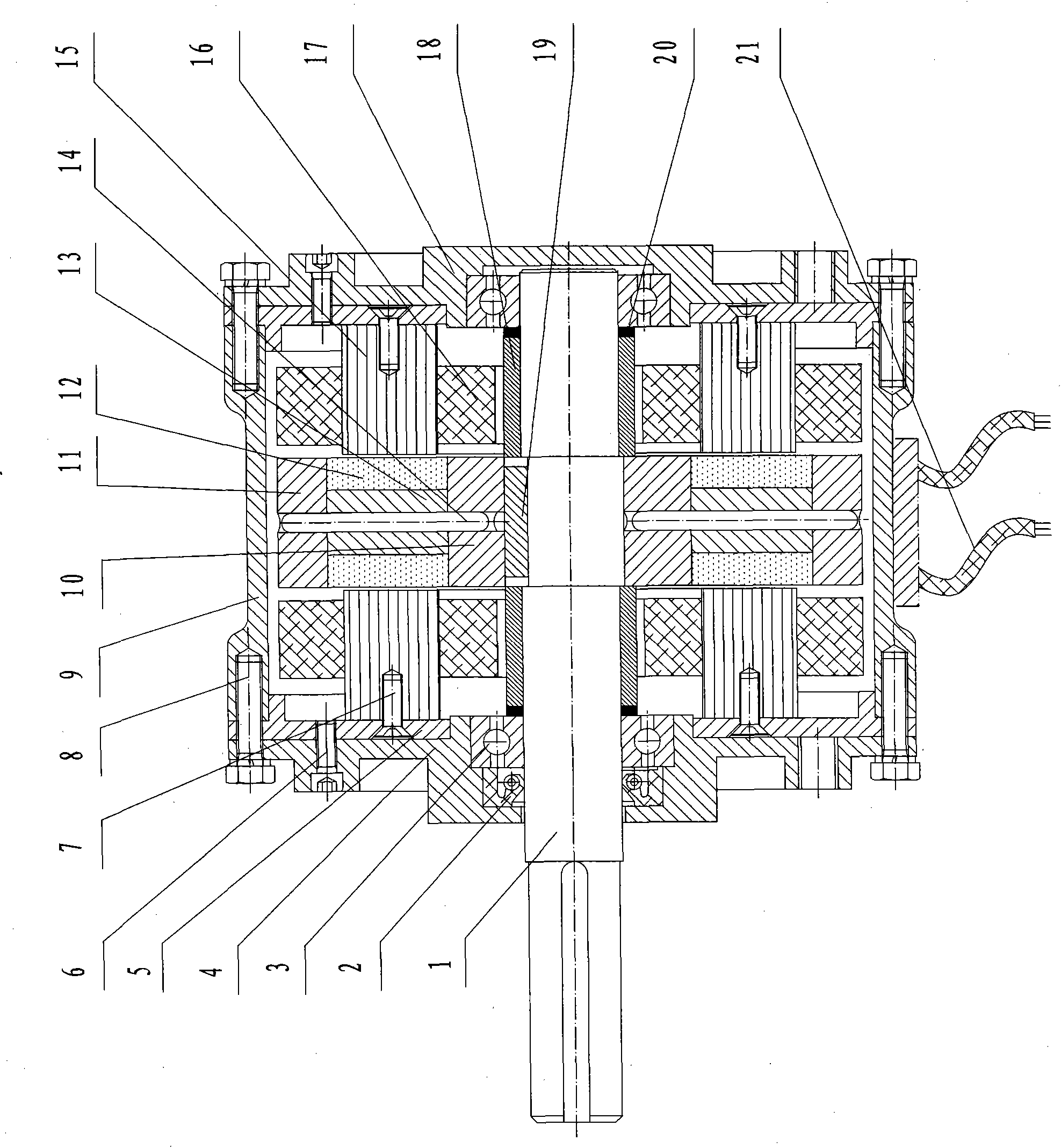
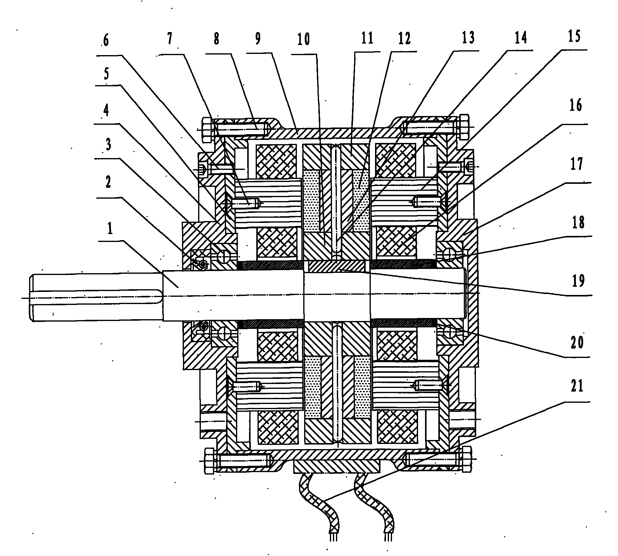
[0023] Such as figure 1 Shown:

[0024] The embedding slots of the stator core (15) are designed on the end face, distributed uniformly and radially along the circumference, the height and slot depth are in the axial direction, and the stacking thickness is in the radial direction; the slot type, number of slots, height, thickness, and motor operating voltage, The output power and working speed match;

[0025] Riveting the magnetic conduction ring (13), the inner magnetic isolation ring (10) and the outer magnetic isolation ring (11) with a naked copper rod (14) into a rigid body;

[0026] Several pieces of rare earth magnets (12) are pasted or embedded in the magnetic ring (13) according to a certain polarity to form a rotor (make one);

[0027] Fix the stator core (15) to the inner end cover (5) with hexagon socket head cap screws (6); embed the stator winding (16) into the stator core (15); align the winding head and end, weld, shape and bind the winding The lead wire (2...


PUM


Abstract

The invention discloses a double-stator single-rotor rare earth permanent magnet motor, which relates to the technical field of motors, in particular to a low-voltage high-power rare earth permanent magnet motor. The motor provided by the invention has two stators and a rotor. The rotor is positioned between the two stators. Armature windings are embedded into wire embedding slots of special rotor cores. A plurality of rare earth magnetic steels are embedded into magnetic conducting rings of the rotor, and provide a multipole magnetic field for air gaps on a left side and a right side. A starting winding and a damping winding are arranged in the rotor. Each stator can drive the rotor to rotate. The two stators can be loaded both simultaneously and respectively, also can be unloaded respectively, and can be controlled in both a direct current way and a frequency modulation mode. The two stators are fixed at the two ends of a housing by a front end cover and a rear end cover. A shaft runs through the rotor and connected with the rotor by a key. The rotor rotates to drive the motor shaft to rotate to output mechanical power. The double-stator single-rotor rare earth permanent magnet motor has the advantages that: sectional areas of a live conducting wire and the winding embedding slots of the cores are ensured; the temperature rise of the motor is controlled; the output power and efficiency are improved; and the designing problems of the low-voltage high-power motor are solved.

Description

technical field [0001] The invention relates to the technical field of motors, in particular to a low-voltage and high-power rare-earth permanent magnet motor. Background technique [0002] For high-power rare-earth permanent magnet motors, whether they are DC motors or three-phase AC motors, if the working environment requires a relatively low working voltage, then high power will inevitably lead to high current, which will bring great difficulties to motor design. [0003] For example, the driving motor used in electric vehicles requires high power. If high voltage is used, low current can be realized, but with high voltage, a large number of power batteries must be connected in series, which will bring difficulties and inconvenience to the mutual matching of battery parameters and safe use; With low voltage, although the number of power batteries connected in series is reduced, the working current will inevitably increase. As the current-carrying conductor, the winding en...

Claims


Application Information

Patent Timeline
Patent Type & Authority Applications(China)
IPC IPC(8): H02K16/04H02K21/12H02K1/16H02K1/27H02K5/04
Inventor 杨中兴张志华蔡书峰张建修
Owner 杨中兴
Why Eureka
Try Eureka