Multiple generator wind turbine

A technology for generators and wind turbines, applied to wind turbine components, engines, wind power generation, etc., can solve problems such as cost and complexity, and achieve the effects of low cost, simple structure, and good lightning protection

Inactive Publication Date: 2010-01-13
WILIC SARL
View PDF7 Cites 6 Cited by
  • Summary
  • Abstract
  • Description
  • Claims
  • Application Information

AI Technical Summary

Problems solved by technology

While this allows the use of two smaller generators to create a high powered wind turbine, the use of a completely separate drive system and power harvesting system introduces undesired expense and complexity to the setup

Method used


Image

  • Multiple generator wind turbine
  • Multiple generator wind turbine
  • Multiple generator wind turbine

Examples


Embodiment Construction

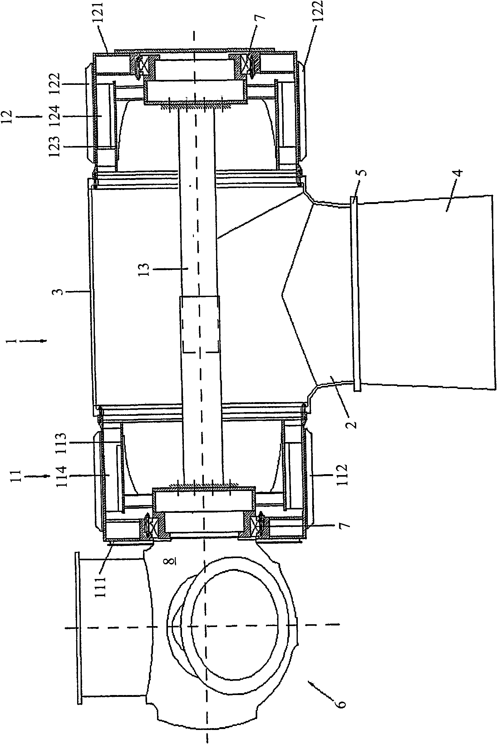
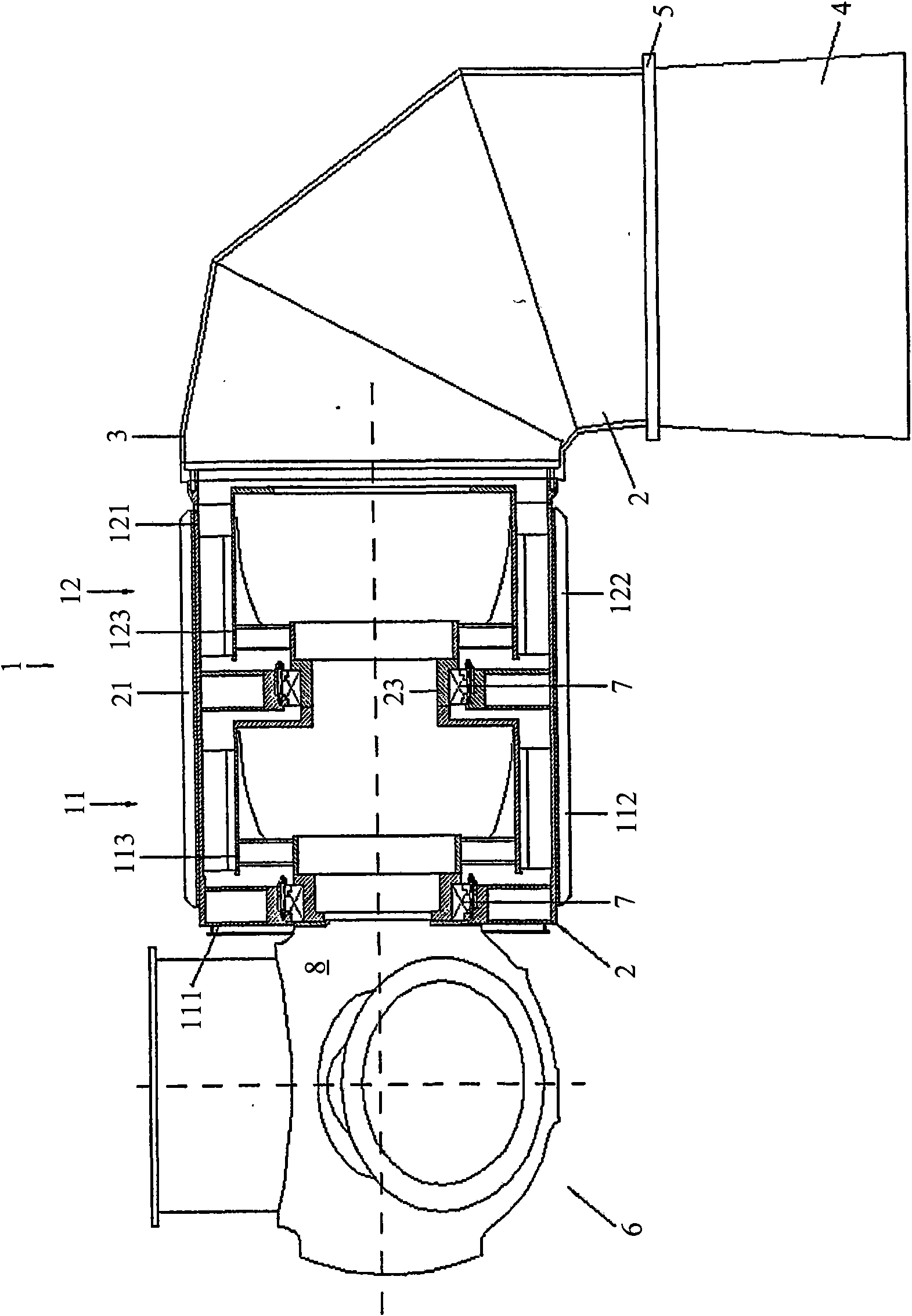
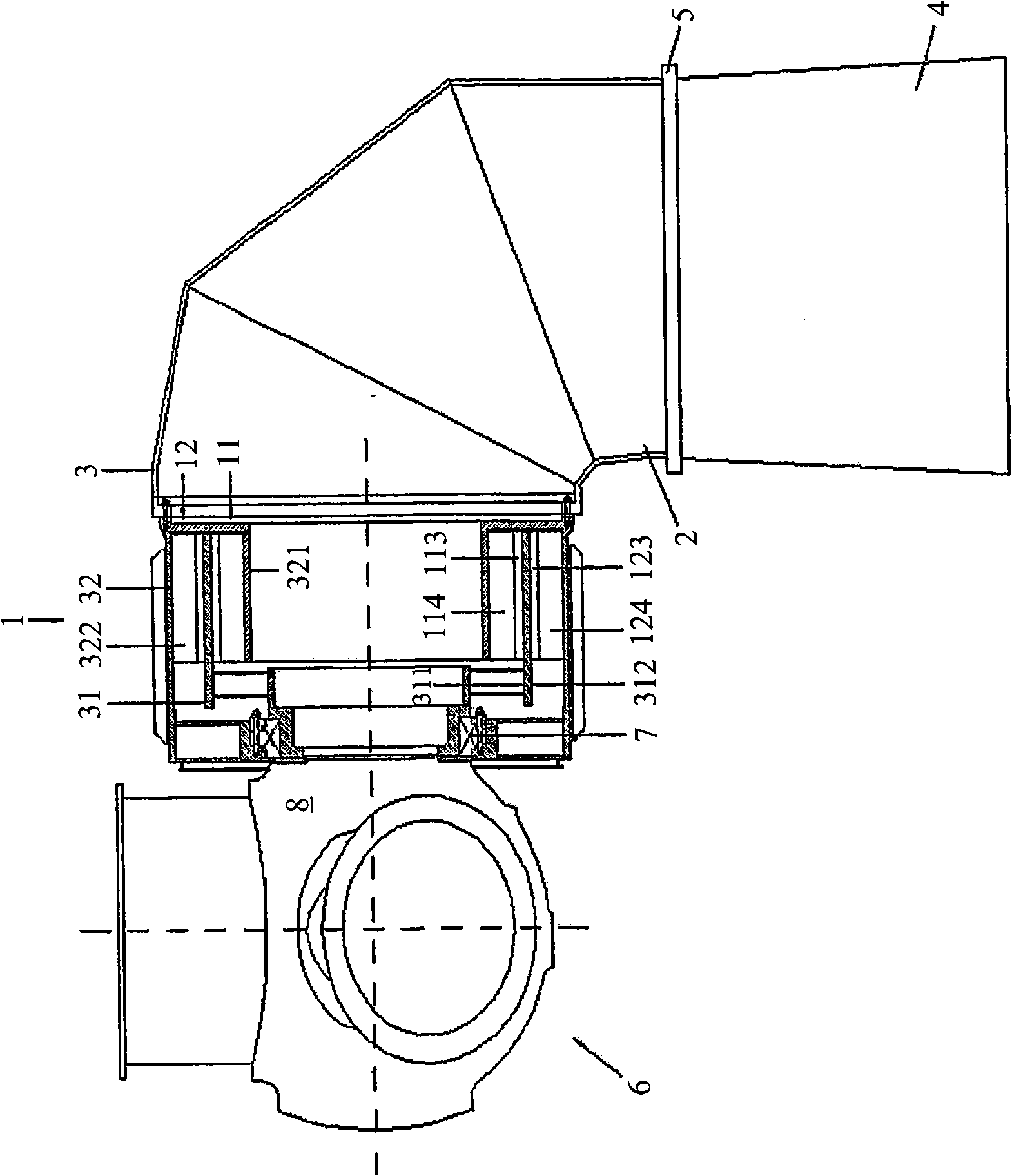
[0039] figure 1 , a multi-generator wind turbine is generally indicated by reference numeral 1 . The support structure 2 of the wind turbine 1 comprises a connection structure 3 placed on top of a support tower 4, preferably with a rotatable connection 5 to allow a single drive blade arrangement 6 to face in the direction of the incoming wind. The blade arrangement 6 comprises a plurality of blades and drives two generators 110 , 120 . Such as figure 1 As shown, the generators 110, 120 may be arranged with one generator 110 on the blade side of the support structure 2 and the other generator 120 on the opposite side of the support structure. The casings 111, 121 of the generators 110, 120 preferably each carry a plurality of circumferentially distributed cooling fins 112, 122 to absorb heat from the generators 110, 120, when the air passes through the cooling fins 112, 122 , releasing heat into the slipstream. The generator 110 on the blade side comprises a rotor 113 conne...


PUM


Abstract

A multiple generator wind turbine employs a single blade arrangement to drive multiple generators. The multiple generators are preferably substantially tubular and can all be mounted on one side of the turbine support structure or can be divided, preferably symmetrically, on opposite sides of the support structure. Preferably, a single drive blade arrangement drives a rotor of a first generator and a shaft connects the first generator to a rotor of a second generator. Additionally, a clutch can be placed in the drive train between two generators to allow turbine operation at lower speeds. The substantially tubular nature of the turbine allows easy access by humans to the interior of the wind turbine and provides ready airflow through the wind turbine to the hub and blades for cooling of equipment therein and / or deicing of the blades.

Description

technical field [0001] The invention relates to a wind generator or turbine. More specifically, embodiments relate to a large wind turbine that includes two or more generators and that allows people to work while providing efficient cooling of components and / or efficient de-icing of blades. Easy access and maintenance. Embodiments are particularly suitable for generating electricity through wind power. Background technique [0002] Wind turbines, especially large generators, include blades mounted on a hub attached to a rotor that rotates when wind passes over the blades. The rotation of this rotor is then used to drive a mechanical device, such as a pump or a generator. For a generator, the rotor will typically carry conductive windings / coils or field generators facing the field generators or conductive windings / coils on the stator, respectively, such that the coil and field generator There is relative motion between them to generate electricity. The field generator is...

Claims


Application Information

Patent Timeline
Patent Type & Authority Applications(China)
IPC IPC(8): F03D9/00F03D1/02
CPCH02K7/1838Y02E10/725F03D11/0025F05B2220/7066Y02E10/722F05B2240/40Y02E10/72F05B2230/601F05B2220/7068H02K7/183F03D9/002F03D1/025F03D9/25F03D80/40Y02E10/728Y02P70/50F03D13/20F03D15/00F03D80/60
Inventor 奥托·帕布斯特
Owner WILIC SARL
Why Eureka
Try Eureka