Hand-eye vision calibration method for robot hole boring system

A robotic hole-making, hand-eye vision technology, applied in instruments, image data processing, measuring devices, etc., can solve problems such as inapplicability to on-site calibration, affecting calibration accuracy, and complex process, achieving high practical value, simple calibration process, and calculation. small amount of effect

Inactive Publication Date: 2010-01-20
BEIHANG UNIV
View PDF0 Cites 77 Cited by
  • Summary
  • Abstract
  • Description
  • Claims
  • Application Information

AI Technical Summary

Problems solved by technology

[0004] Most of the previous hand-eye vision calibration methods solve the internal and external parameters of the camera at the same time. The process is complex and requires solving a large number of matrix homogeneous transformation equations AX=XB (Y.C.Shiu and S.Ahmad, "Calibration of wrist-mounted robotic sensors by solving homogeneous transform equations of the form AX=XB”, IEEE Trans.Robot.Automat., vol.5, pp.16-29, Feb.1989), these methods will eventually affect the calibration accuracy due to the accumulation of computer rounding errors during the calculation process
In addition, three-coordinate measuring equipment can be used for hand-eye calibration (Zhou Fuqiang, Zhang Guangjun, on-site double theodolite three-dimensional coordinate measuring system [J]. Chinese Journal of Mechanical Engineering, vol.40, No.1, 2004, pp.165-169 ), but this method is expensive and not suitable for on-site calibration in industrial environments

Method used


Image

  • Hand-eye vision calibration method for robot hole boring system
  • Hand-eye vision calibration method for robot hole boring system
  • Hand-eye vision calibration method for robot hole boring system

Examples


Embodiment

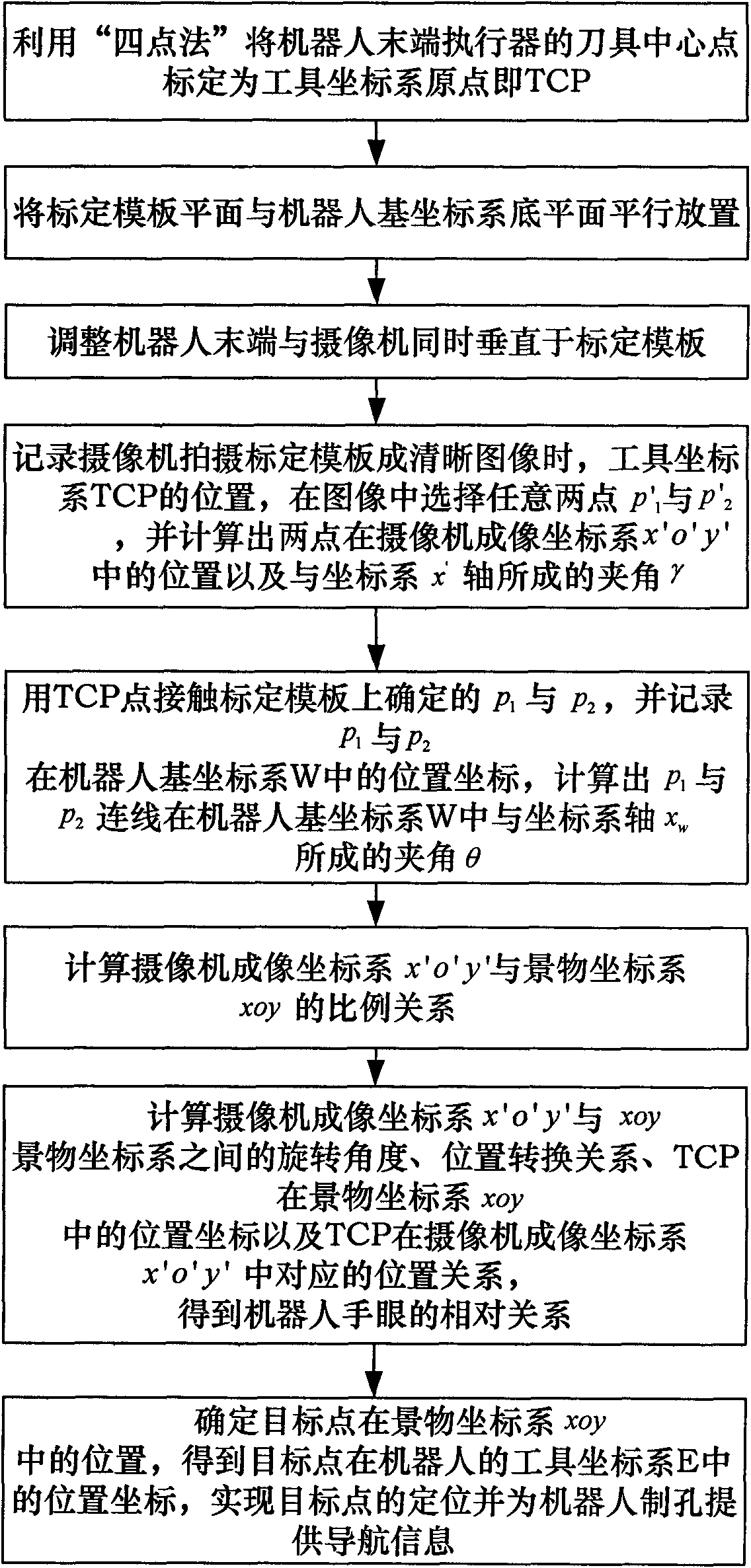
[0093] Apply the method described in the present invention, at first carry out hole making with end effector to obtain the actual position coordinates of the hole, then use camera to shoot, carry out positioning to obtain the positioning coordinates of the hole and calculate the positioning error, the data are as shown in Table 1:

[0094] Table 1 Positioning error data table

[0095] Group

No

actual coordinates

Positioning coordinates

Δx / mm

Δy / mm

positioning error

E / mm

1

(1168.24,-5.19)

(1168.25,-5.16)

0.01

0.03

±0.03

[0096] 2

(1176.87,-81.80)

(1176.99,-81.77)

0.12

0.03

±0.12

3

(1132.69,-35.58)

(1132.87,-35.44)

0.18

0.14

±0.23

4

(1086.87,-8.79)

(1087.01,-8.68)

0.14

0.11

±0.18

5

(1135.85,-66.08)

...


PUM


Abstract

The invention discloses a hand-eye vision calibration method for a robot hole boring system, and the hand-eye vision calibration method comprises the steps of firstly calibrating an origin point of a coordinate system of a tool on an end effector of the robot, that is TCP, establishing a scene coordinate system in a shot plane, then shooting two points in the plane, using the TCP to contact the two points, further obtaining the relationship between an imaging coordinate system of a camera and the scene coordinate system and utilizing the relationship to calculate the position relationship of the TCP in the scene coordinate system. Finally, the position relationship between the TCP and the imaging coordinate system of the camera, that is the hand-eye relationship, is indirectly obtained by taking the scene coordinate system as an intermediate conversion coordinate system. The hand-eye vision calibration method ignores depth information of the camera in the hand-eye relationship and transforms the calibration process into the geometric relationship, the calibration process is simple, the calculation amount is small, an expensive three-coordinate measuring device is unnecessary, and the precision is higher, thereby having higher practical value and being capable of meeting the practical working needs of the robot hole boring system.

Description

technical field [0001] The invention relates to a hand-eye vision calibration method for a robot hole-making system, belonging to the field of advanced manufacturing and automation. Background technique [0002] As a relatively new automation technology, robotic hole making system is of great significance to aircraft manufacturing and other industrial fields that require a large number of holes. In order to realize the intelligence and flexibility of the robot hole making system, it is necessary to install a vision system for the robot. The vision system can provide navigation and positioning information for the robot's hole-making process. [0003] In the prior art, robot vision mainly includes two types of visual sensing methods: laser vision or camera vision. The former mainly uses equipment such as laser trackers to obtain target point position information, which is characterized by high precision, but the equipment is expensive and the information obtained is relative...

Claims


Application Information

Patent Timeline
Patent Type & Authority Applications(China)
IPC IPC(8): G06T7/00G01C21/00
Inventor 战强王祥毕树生姚艳杉宗光华
Owner BEIHANG UNIV
Why Eureka
Try Eureka