Method, device and system for transmitting synchronous clock
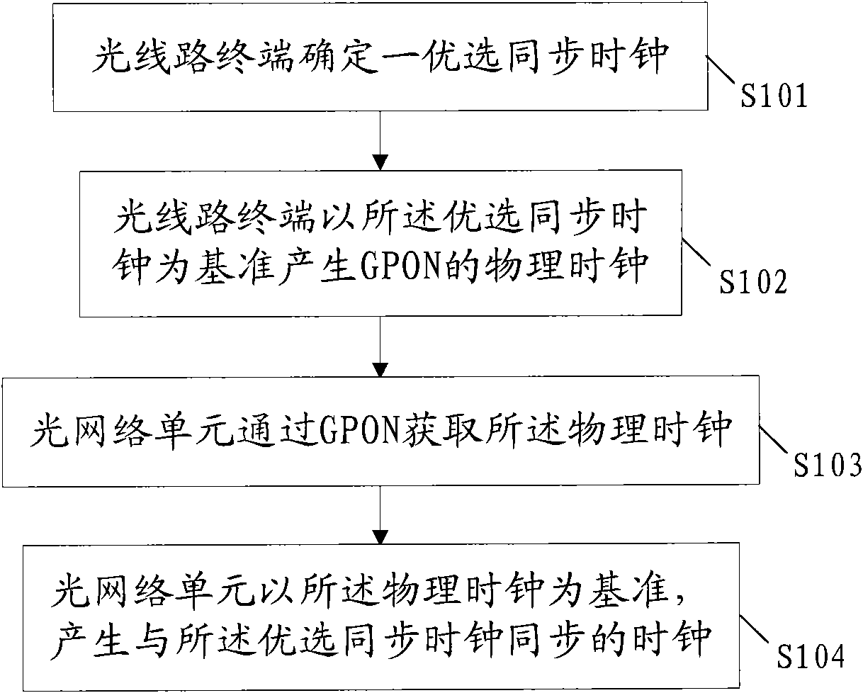
A technology for synchronizing clocks and clocks, applied in the field of optical communication, can solve the problems of large jitter and drift of fd, inability to transmit synchronous clocks at the same time, and inability to transmit synchronous clocks, etc., to achieve high-quality transmission effects
- Summary
- Abstract
- Description
- Claims
- Application Information
AI Technical Summary
Problems solved by technology
Method used
Image
Examples
Embodiment 1
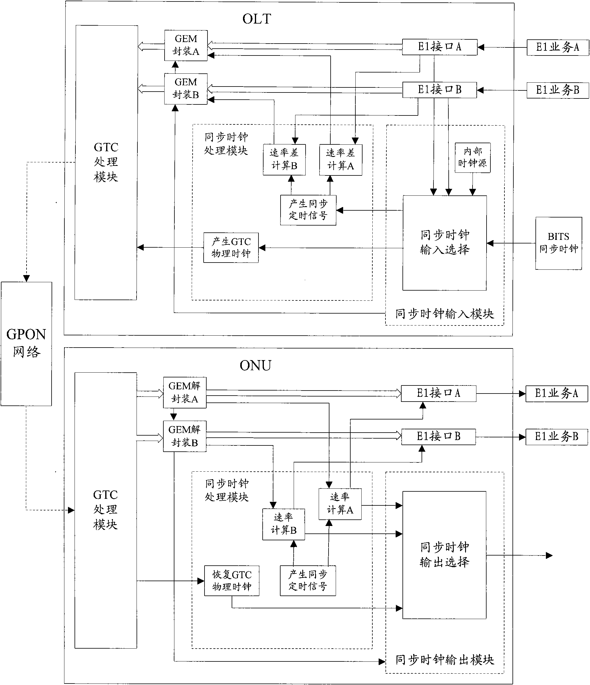
[0049] In this embodiment, two channels of E1 services are transmitted at the same time, and the two channels of E1 services respectively carry different synchronous clocks when output by the ONU. Such as figure 2 As shown, the specific implementation process of this embodiment is as follows:
[0050] S201: The synchronous clock input module of the OLT selects BITS or a certain E1 input as the synchronous clock source according to the synchronous clock quality information or according to user settings, and sends it to the synchronous clock processing module;
[0051] S202: Generate a synchronous timing signal inside the OLT according to the selected synchronous clock;
[0052] S203: According to the selected synchronous clock, generate 8KHz and 155.52MHz GPON physical clocks synchronous with the synchronous clock, and send them to the GTC processing module of the OLT;
[0053] S204: Calculate the rate difference between the two E1 services and the synchronous timing signal;...
Embodiment 2
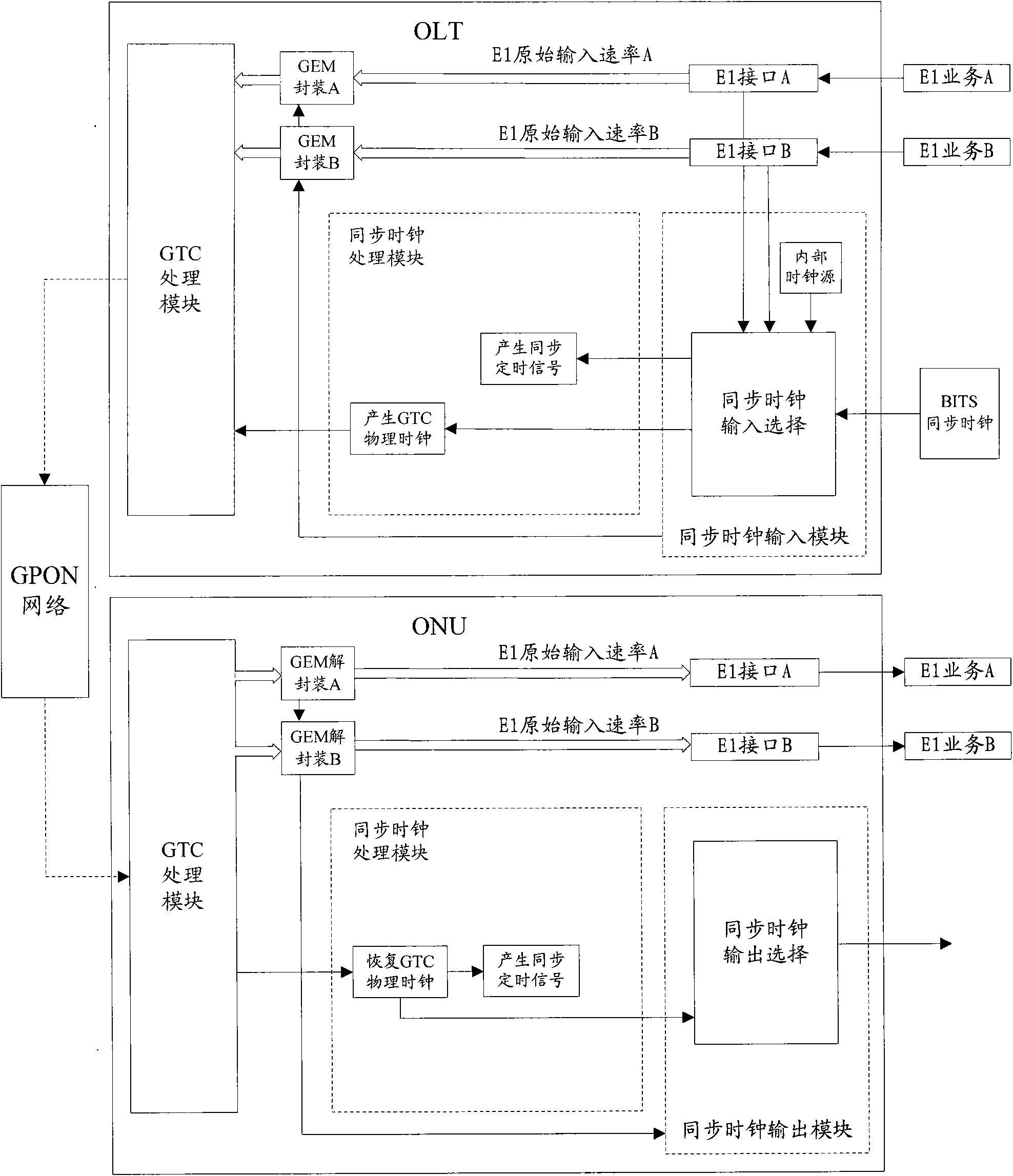
[0069] In this embodiment, two channels of E1 services are transmitted at the same time, and the two channels of E1 services respectively carry different synchronous clocks when output by the ONU. Different from Embodiment 1, this embodiment directly encapsulates and decapsulates the original input rate of E1, without calculating the rate difference between E1 and the synchronous timing signal. Such as image 3 As shown, the specific implementation process of this embodiment is as follows:
[0070] S301-S303: same as steps S201-S203;
[0071] S304: Send the original input rate of the E1 and the synchronous clock quality information together to the GEM encapsulation module, and the GEM encapsulation module encapsulates the original input rate of the E1, the synchronous clock quality information and the E1 service data flow into a GEM frame, transmitted to the ONU, wherein the synchronization clock quality information is optional;
[0072] Wherein, the process of GEM encapsul...
Embodiment 3
[0080] In this embodiment, the GPON network transmits two E1 services at the same time, and the two E1 services carry the same synchronous clock when output by the ONU. The specific implementation process of this embodiment is the same as the implementation process described in Embodiment 1, and will not be repeated here. Wherein, the rate difference between the two E1 services and the synchronous timing signal in the step S204 is always zero.
[0081] Of course, this embodiment can also be similar to Embodiment 2, and directly encapsulate and decapsulate the original input rate of E1 without calculating the rate difference between E1 and the synchronous timing signal. For the specific implementation process, refer to Embodiment 1 and Implementation Example 2 will not be repeated here.
PUM
 Abstract
Description
Claims
Application Information
 - R&D
- Intellectual Property
- Life Sciences
- Materials
- Tech Scout
- Unparalleled Data Quality
- Higher Quality Content
- 60% Fewer Hallucinations
Browse by: Latest US Patents, China's latest patents, Technical Efficacy Thesaurus, Application Domain, Technology Topic, Popular Technical Reports.
© 2025 PatSnap. All rights reserved.Legal|Privacy policy|Modern Slavery Act Transparency Statement|Sitemap|About US| Contact US: help@patsnap.com


