

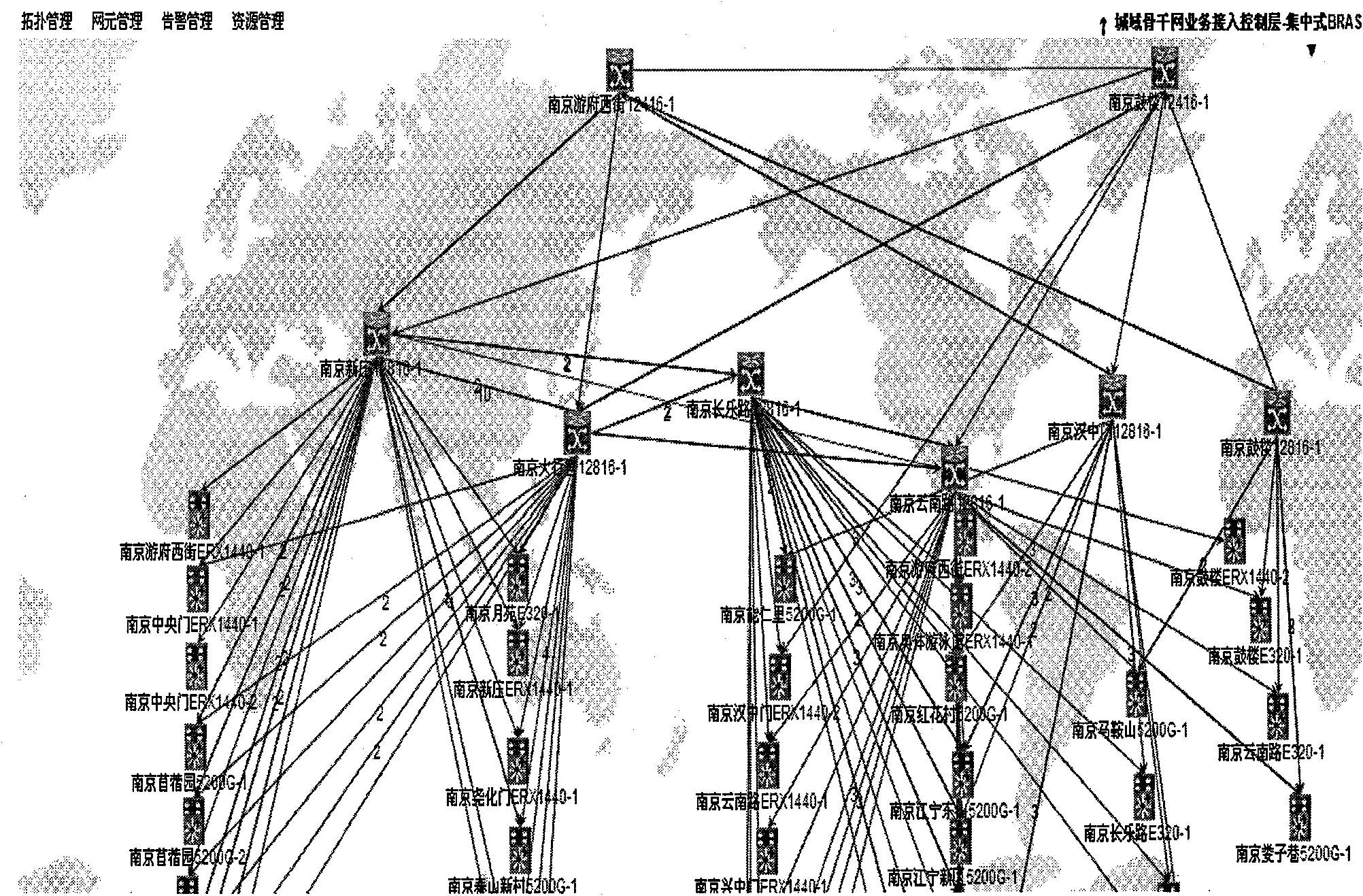
Network topology structure showing method based on plane mode
A technology of network topology and planar mode, applied in the direction of data exchange network, digital transmission system, electrical components, etc., can solve the problems of not being humanized enough, unable to reflect the topology, and the huge interconnection structure of the metropolitan area network, so as to improve maintenance efficiency , Improve monitoring efficiency, improve the effect of sorting efficiency
- Summary
- Abstract
- Description
- Claims
- Application Information
AI Technical Summary
Problems solved by technology
Method used
Image

Examples
Embodiment Construction
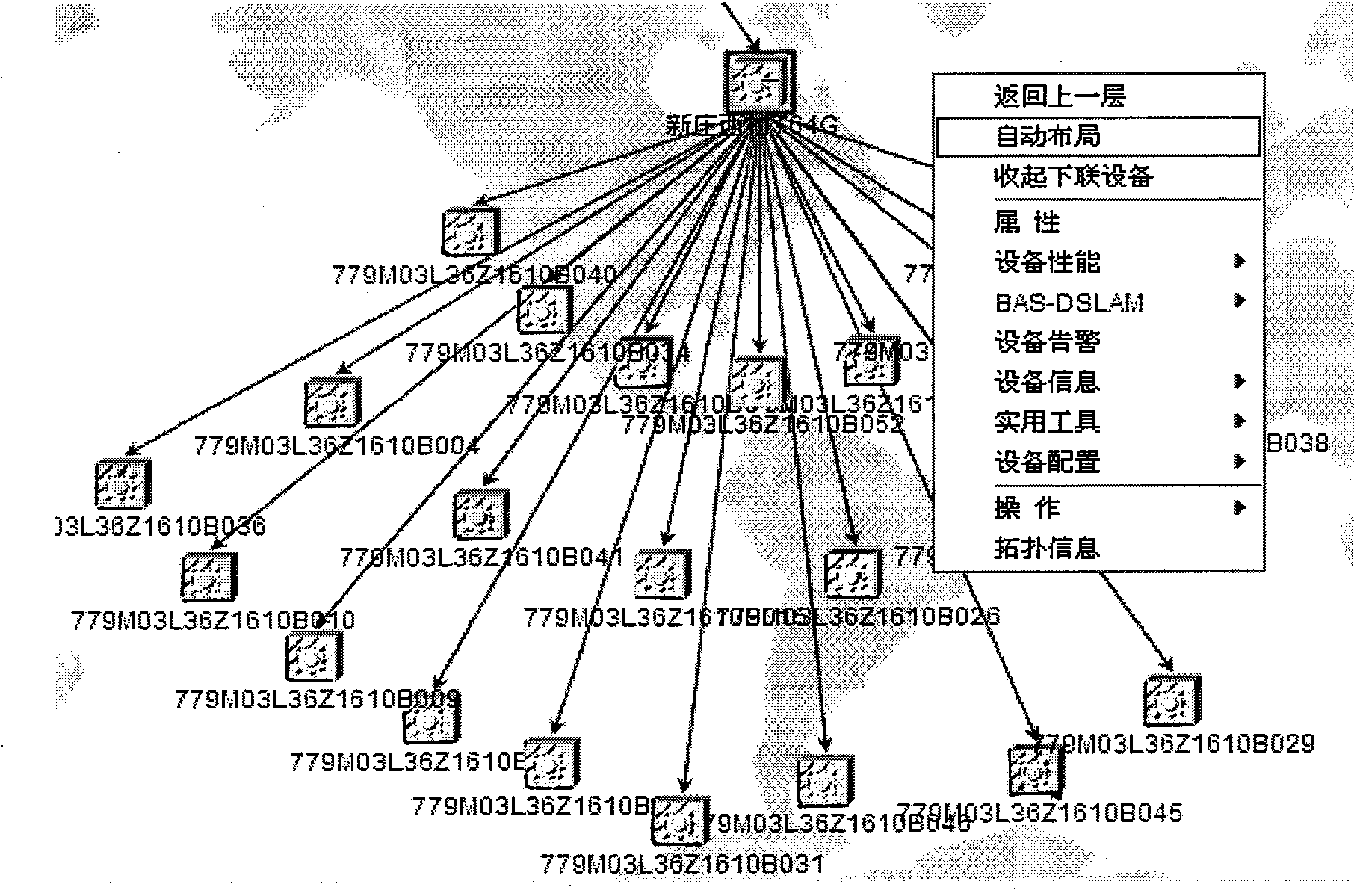
[0057] The present invention will be further described below in conjunction with the accompanying drawings and embodiments. The network element data of the plane topology map requires an independent module in the background to put the discovered results into the database through a series of algorithms, and notify the main control module to generate the topology map, and set the coordinates in sequence according to the order of the resource hierarchy. The detailed implementation steps are as follows:
[0058] 1) Read the device information from the database, construct each device information into a separate network element object, save the device name, device IP, device model, etc., and load it into the resource level of the entire system, according to the resource level Equipment network element objects set coordinates in sequence.
[0059] 2) Load link resources from the database, store the uplink and downlink devices of the device in the device object according to the link ...
PUM
 Abstract
Description
Claims
Application Information