Floating hydraulic generator

A hydro-generator and pulley technology, which is applied in hydropower stations, engine components, machines/engines, etc., can solve the problems of low utilization rate of hydrodynamic energy resources, loss of hydrodynamic energy, and unfavorable navigation.

Inactive Publication Date: 2010-01-27
王川
View PDF0 Cites 2 Cited by
  • Summary
  • Abstract
  • Description
  • Claims
  • Application Information

AI Technical Summary

Problems solved by technology

In hydraulic turbines of various subcategories such as impact type and impact type, there may be an inclination angle between the guide vane and the direction of water flow to cause the loss of kinetic energy of the water, or it is not suitable for the construction of large and medium-sized generators and power stations in terms of technical structure, or in the construction of large Medium-sized hydroelectric generators and power stations need to build barrages; blocking or not conducive to navigation, and have high requirements for water conservancy conditions. For example, in the river basins in the vast plains of our country, although the water flow between intervals is small, the water flow is rich, but there are no mountains on both sides of the bank. The geographical conditions are not suitable for building barrages, such as the plain water basins of the Yangtze River and the Yellow River, as well as areas such as coastlines and bays that use seawater tidal power generation. With the existing technology, large and medium-sized hydroelectric generators and power stations can be built in the above-mentioned areas. The kinetic energy resource utilization rate of water flow is low

Method used


Image

  • Floating hydraulic generator
  • Floating hydraulic generator
  • Floating hydraulic generator

Examples


Embodiment Construction

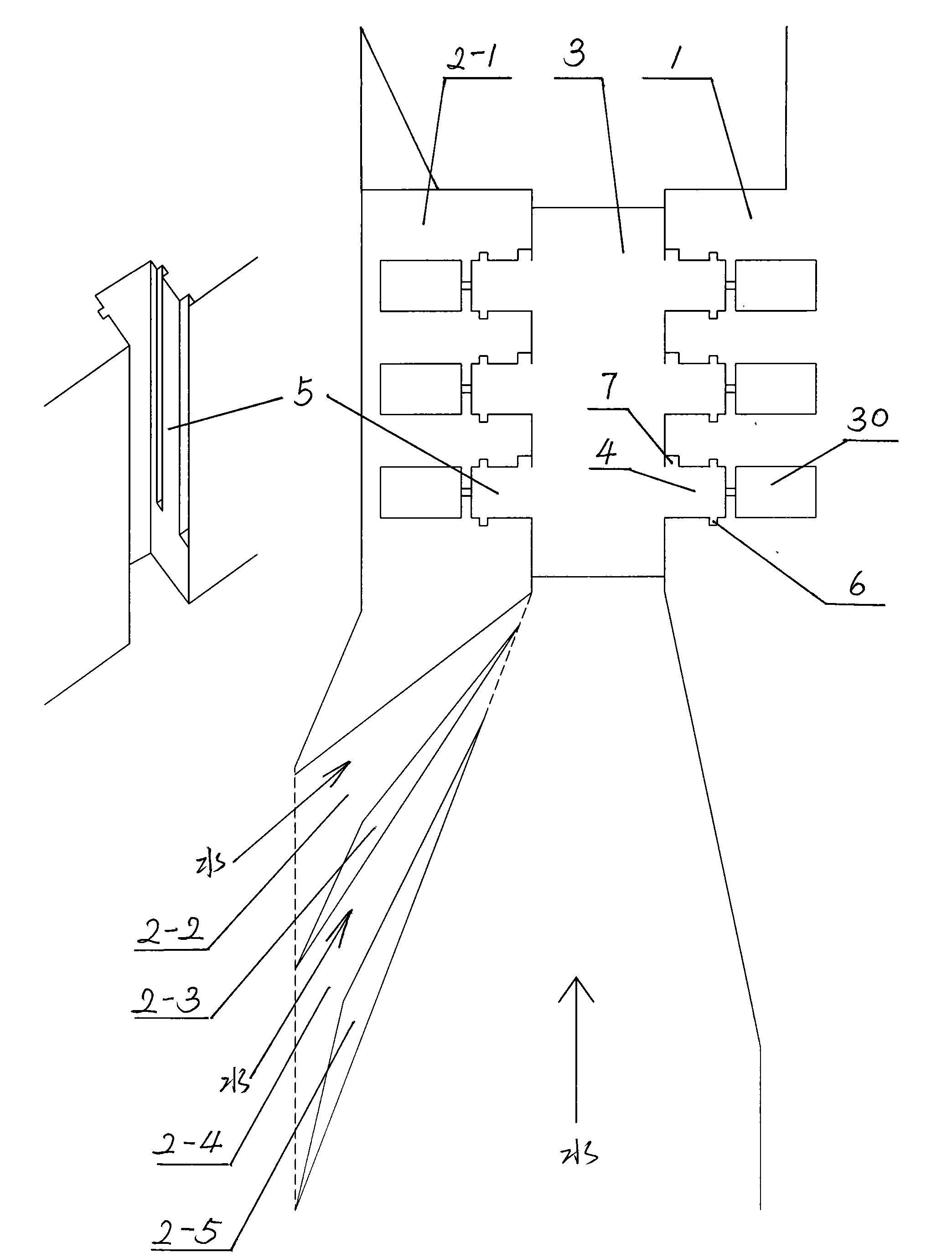
[0032] Such as figure 1 , Build reinforced concrete lathe in river: build main frame 1 on one bank of river, also can build main frame in the river channel of offshore as river course width is big. Separate sub-frames 2-1, 2-3, and 2-5 are built in a certain span horizontally with the main frame in the river channel; they can be arranged continuously depending on the flow conditions and needs. The main frame and the auxiliary frame form a water flow channel in the machine tool that is wide upstream, narrow downstream, and finally gradually wider. Water replenishment channels 2-2, 2-4 are arranged alternately with auxiliary machine bases 2-1, 2-3, and 2-5; if the main base is also built in an offshore river instead of leaning against a certain bank, then its The configuration stands opposite to the sub-frame and is congruent (figure omitted). The water inlet of the supplementary channel is wide, upstream of the river water flow direction, and the water outlet is narrow, downs...


PUM


Abstract

The invention provides a floating hydraulic generator, and belongs to the field of hydraulic generators. In the generator, a machine tool is arranged in a flowing water area; a main frame is connected with a top pulley, a bottom pulley and a float chamber on a slideway of the machine tool; a water wheel shaft with a guide vane is connected with the main frame, and is connected with a vertical axis, a spool bearing, a slide turnplate, an axle tube and a grabbing arm gear in order through a conical transmission gear box; and a torque is transmitted to a rotor shaft of the generator through gear engagement. The floating hydraulic generator can normally generate electricity along with spontaneous fluctuation of the water level without constructing a barrage, improving the water level or blocking sea traffic, and can utilize self power of water flow to dredge, concentrate and accelerate the water flow; and a generator set consisting of the generator can multiply and sufficiently utilize the kinetic energy of the accelerated water flow. The generator is more suitable for constructing large-medium sized floating hydraulic generator sets by utilizing tidal seawater bidirectional water flow energy in river basins of plains under a condition that no mountain exists on both sides of rivers, coastlines and bay areas. The floating hydraulic generator has high utilization rate of water flow energy, and great energy conversion value in unit time.

Description

Technical field: [0001] The invention relates to an electromagnetic device for converting hydrokinetic energy into electric energy, belonging to the field of hydraulic generators. technical background: [0002] Current hydroelectric generator and prior art: the position of its water turbine is relatively fixed, and after both water turbine is designed and installed, it does not rise and fall with the natural fluctuation of water level. In hydraulic turbines of various subcategories such as impact type and impact type, there may be an inclination angle between the guide vane and the direction of water flow to cause the loss of kinetic energy of the water, or it is not suitable for the construction of large and medium-sized generators and power stations in terms of technical structure, or in the construction of large Medium-sized hydroelectric generators and power stations need to build barrages; blocking or not conducive to navigation, and have high requirements for water con...

Claims


Application Information

Patent Timeline
IPC IPC(8): F03B13/00F03B3/16F03B11/00F03B11/06E02B9/00
Inventor 王川
Owner 王川
Why Eureka
Try Eureka