Device and method for debugging emitter position of ceilometer

A debugging method and transmitter technology, which is applied in the direction of the instrument, can solve the problems of placing the transmitter error, etc., and achieve the effect of convenient method and high cost performance

Active Publication Date: 2010-01-27
CAMA LUOYANG ENVIRONMENTAL MEASUREMENT
View PDF3 Cites 5 Cited by
  • Summary
  • Abstract
  • Description
  • Claims
  • Application Information

AI Technical Summary

Problems solved by technology

However, beams with different wavelengths have different focus positions, so beams with exactly the same wav

Method used


Image

  • Device and method for debugging emitter position of ceilometer
  • Device and method for debugging emitter position of ceilometer
  • Device and method for debugging emitter position of ceilometer

Examples


Embodiment Construction

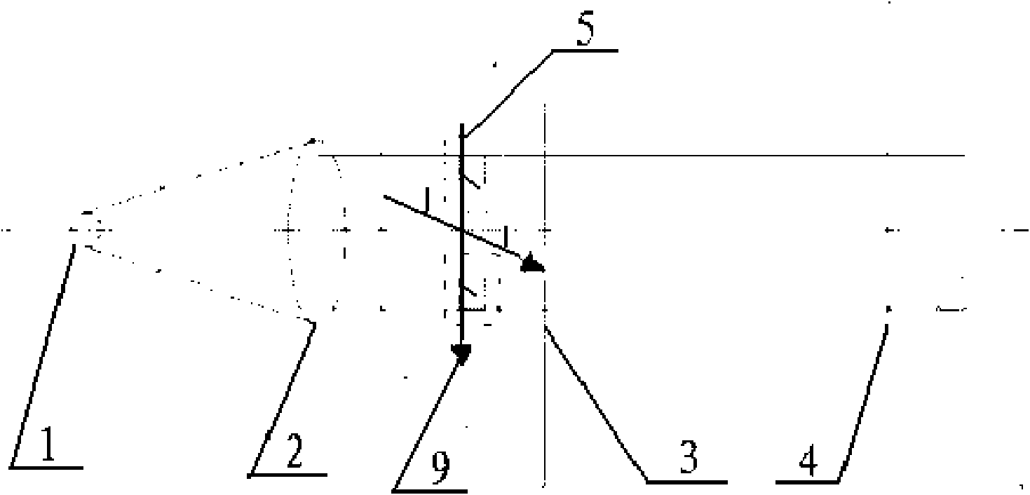
[0020] Such as figure 1 The shown debugging device of the present invention comprises a ceilometer, which is provided with a transmitter 1 and a lens 2, and the device also includes a debugging board 3 and a plane mirror 4 which are successively arranged on the optical axis of the lens, and the debugging There are two symmetrical holes with the optical axis of the lens as the axis of symmetry within the position corresponding to the aperture of the lens on the plate 3, the above-mentioned plane mirror 4 and the debugging board 3 are arranged perpendicular to the optical axis of the lens, and the light spot 5 is reflected and emitted by the plane mirror 4 The reflected spot of the light beam emitted by the device 1 on the debugging board 3 with two holes corresponds to the position of the lens 2 on the debugging board 3, with the optical center of the lens 2 as the origin, and the horizontal line and the vertical line passing through the origin as the origin respectively. Two-d...


PUM


Abstract

The invention relates to a device and a method for debugging emitter position of a ceilometer. The method comprises the following steps: (1) placing the emitter at a theory position of the focus of a lens so that the emitter emits light rays; (2) after a debugging plate generates reflecting light spots reflected by a plane mirror when light beams to be emitted pass through holes of the debugging plate and shine on the plane mirror, moving the plane mirror so that the light spots of different holes fall on the holes positioned on corresponding position of the debugging plate; (3) debugging the position of the emitter according to the relative positions of the reflecting light spots falling on the debugging plate so that the central positions of the reflecting light spots of the different holes are overlaid with the centers of the corresponding holes, the light spots are minimum, and the emitter is positioned at the focus position, i.e. an optimal placed position of the emitter of the ceilometer, of the lens at the time. The method which determines the focus position of the lens by measuring the size of an image has high precision, is convenient and easy to operate and can accurately determine the focus position of the lens, thereby determining the optimal placed position of the emitter.

Description

technical field [0001] The invention relates to an optical debugging technology, in particular to a debugging device and a debugging method for the focus position of a lens. Background technique [0002] In order to make the spread angle of the emitted beam of the laser transmitter as small as possible, a lens is added behind the emitter. In order to make the emitted beam parallel, the emitter needs to be placed at the focal point of the lens, but the actual focal length of the lens and the theoretical value are quite large. Therefore, a reliable and high-precision debugging method and debugging device must be used to determine the position of the lens focus. [0003] At present, the common debugging method is to let a beam of light pass through the collimator, then obtain a beam of parallel light, and then let the parallel light pass through the lens to find the focus of the lens. However, beams with different wavelengths have different focus positions, so beams with exact...

Claims


Application Information

Patent Timeline
IPC IPC(8): G01W1/18
Inventor 滕军肖巧景佟增亮
Owner CAMA LUOYANG ENVIRONMENTAL MEASUREMENT
Why Eureka
Try Eureka