Eureka AIR delivers breakthrough ideas for toughest innovation challenges, trusted by R&D personnel around the world.

Integrated high-frequency electrodeless lamp

An electrodeless lamp, high-frequency technology, applied in the use of gas discharge lamps, parts of gas discharge lamps, discharge lamps, etc., can solve the problems of increasing the cost of high-frequency electrodeless lamps, occupying space, and poor heat dissipation. Achieve excellent heat dissipation effect, beautiful appearance and effective heat dissipation

Inactive Publication Date: 2010-01-27
丁春辉
View PDF0 Cites 7 Cited by
  • Summary
  • Abstract
  • Description
  • Claims
  • Application Information

AI Technical Summary

Problems solved by technology

[0002] At present, the high-frequency electrodeless light bulbs and high-frequency generators on the market are designed separately, which not only takes up space, but also is inconvenient to install, and does not match the traditional lamp head, and the cost is high.
For the part of the high-frequency electrodeless bulb, the traditional high-frequency electrodeless bulb has an exhaust pipe and an amalgam storage tube, and these two tubes are respectively located on both sides of the bottom of the discharge chamber. And the amalgam storage tube, which requires that the high-frequency electrodeless lamp must have a large enough volume, which not only increases the cost of manufacturing high-frequency electrodeless lamps, but also limits the development of high-frequency electrodeless lamps in a wider direction
Most of the current high-frequency electrodeless lamps use heat-conducting rods and bases for heat dissipation, and the heat dissipation effect is not good. However, the high-frequency electrodeless lamps have higher power and generate more heat. High-frequency electrodeless lamps with poor heat dissipation will seriously affect its lifespan

Method used


Image

  • Integrated high-frequency electrodeless lamp
  • Integrated high-frequency electrodeless lamp
  • Integrated high-frequency electrodeless lamp

Examples


Embodiment Construction

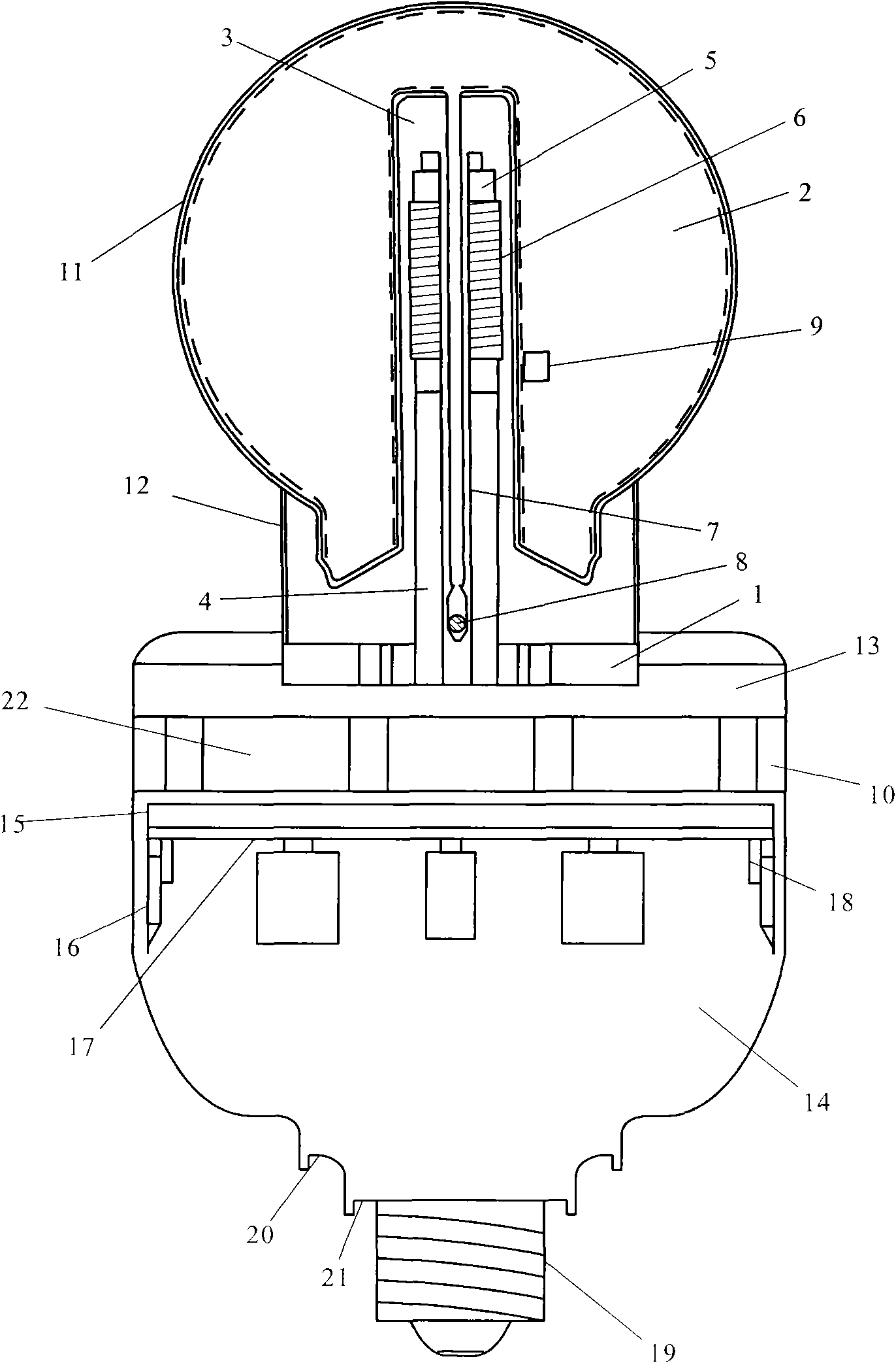
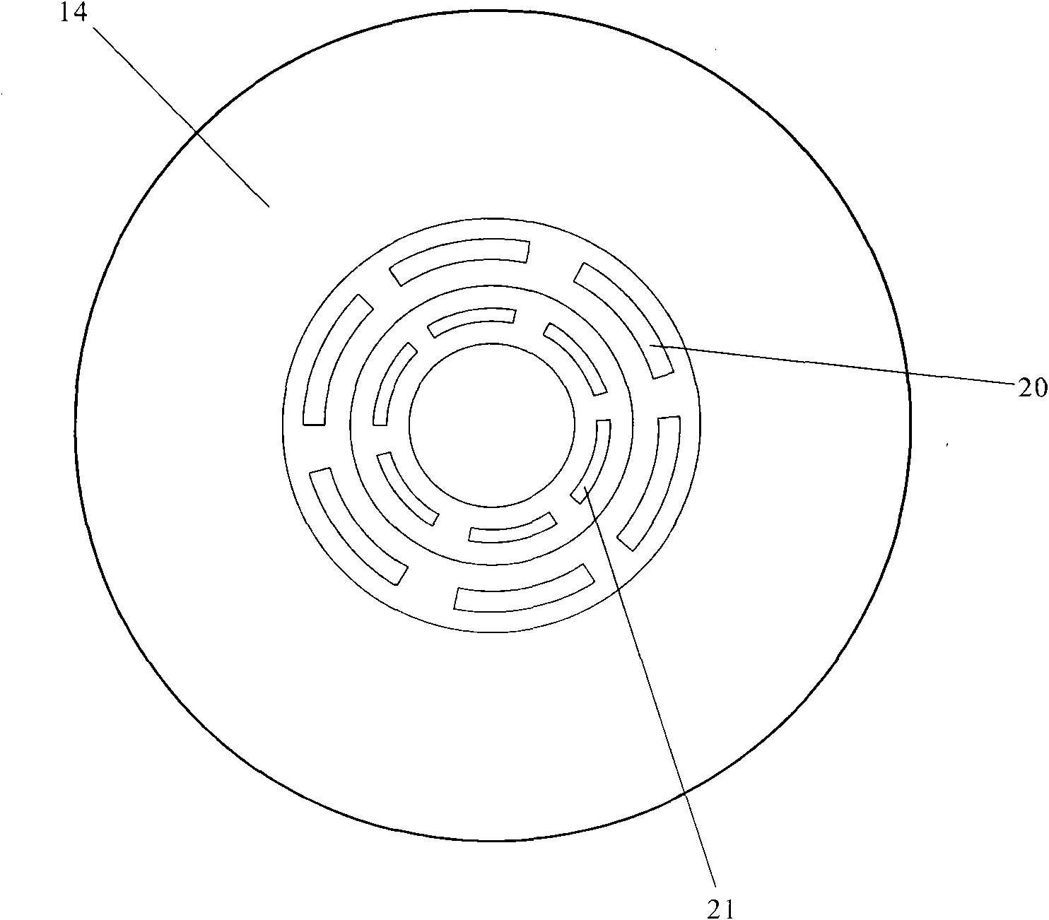
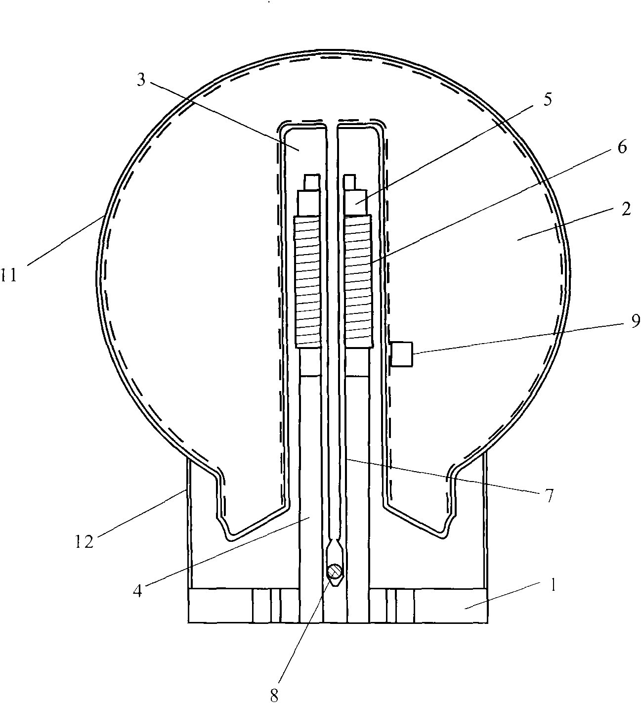
[0018] Please refer to Figure 1 to Figure 3 , figure 1 It is a cross-sectional view of the integrated high-frequency electrodeless lamp of the present invention, figure 2 is a top view of the present invention, image 3 It is a cross-sectional view of the high-frequency electrodeless lamp of the present invention. As shown in the figure, the integrated high-frequency electrodeless lamp has a high-frequency generator as a head and a high-frequency electrodeless bulb mounted on the high-frequency generator, wherein the high-frequency generator further includes a high-frequency generator for installing The lower shell 13, the middle heat insulation seat 10, the upper shell 14 and the lamp holder 19 installed on the upper shell 14 for connecting an external power source of the high frequency induction lamp, the middle heat insulation seat 10 and the upper shell 14 form a space that can accommodate In the cavity of the power cooling base 15, the circuit module 17 of the high f...


PUM


Abstract

The invention relates to an integrated high-frequency electrodeless lamp. The integrated high-frequency electrodeless lamp is provided with a high-frequency generator as a head and a high-frequency electrodeless bulb installed on the high-frequency generator, wherein the high-frequency generator further sequentially comprises a lower shell for mounting the high-frequency electrodeless lamp, a middle heat insulating seat, an upper shell and a lamp holder connected with an outside power source and installed on the upper shell, the middle heat insulating seat and the upper shell form a cavity capable of containing a power source heat dissipation base, a circuit module of the high-frequency generator is arranged on the power source heat dissipation base, and a field effect transistor on the circuit module clings against a connecting pin on the power source heat dissipation base. In the invention, the high-frequency generator and a high-frequency electrodeless bulb shell are integrally designed so as to save the occupied volume and have easy installation.

Description

technical field [0001] The invention relates to an integrated high-frequency electrodeless lamp. Background technique [0002] At present, the high-frequency electrodeless bulbs and high-frequency generators on the market are of separate design, which not only takes up space and volume, but also is inconvenient to install, and does not match the traditional lamp head, and the cost is high. For this part of the high-frequency electrodeless bulb, the traditional high-frequency electrodeless bulbs all have an exhaust pipe and an amalgam storage pipe, which are located on both sides of the bottom of the discharge chamber. And the amalgam storage tube, which requires the high-frequency induction lamp to have a large enough volume, which not only increases the cost of manufacturing the high-frequency induction lamp, but also limits the wider development of the high-frequency induction lamp. Most of the current high-frequency induction lamps use heat conduction rods and bases to d...

Claims


Application Information

Patent Timeline
Patent Type & Authority Applications(China)
IPC IPC(8): H01J65/00H01J5/50H01J61/52H01J61/56H01J61/42H01J61/24H05B41/24H05B41/285
CPCY02B20/183Y02B20/00
Inventor 丁春辉
Owner 丁春辉
Why Eureka
Eureka Blog
Learn More