
Reversal stubble burying rotary cultivator

A technology of rotary tiller and rotary tiller, which is applied in the direction of tillage implements, agricultural machinery and implements, shovels, etc. It can solve the problems of high power consumption of the unit, increased power consumption, and poor surface flatness.

Inactive Publication Date: 2010-02-03
王森豹
View PDF0 Cites 2 Cited by
  • Summary
  • Abstract
  • Description
  • Claims
  • Application Information

AI Technical Summary

Problems solved by technology

[0002] At present, the reverse stubble burying rotary tiller uses the rotary tiller shaft to reversely cut the soil. Through the function of the fender, the rotary-cut soil is thrown to the rear. The straw is blocked by the fence and falls in front of the fence, and the soil is scattered through the fence. Falling on the straw to achieve the effect of stubble, because the front fender needs a certain distance from the ground, the loose soil in front of the rotary tiller shaft is turned and piled up on both sides of the machine during reverse rotary cutting, forming two numbers A long ridge with a height of one centimeter and a width of more than ten centimeters forms small mounds at the turns and turns. The depth of rotary tillage increases the loose soil and covers the straw, which increases the power consumption. At present, the reverse stubble burying rotary tiller has defects such as high unit power consumption, high damage rate, and poor surface flatness.

Method used


Image

  • Reversal stubble burying rotary cultivator
  • Reversal stubble burying rotary cultivator

Examples


Embodiment Construction

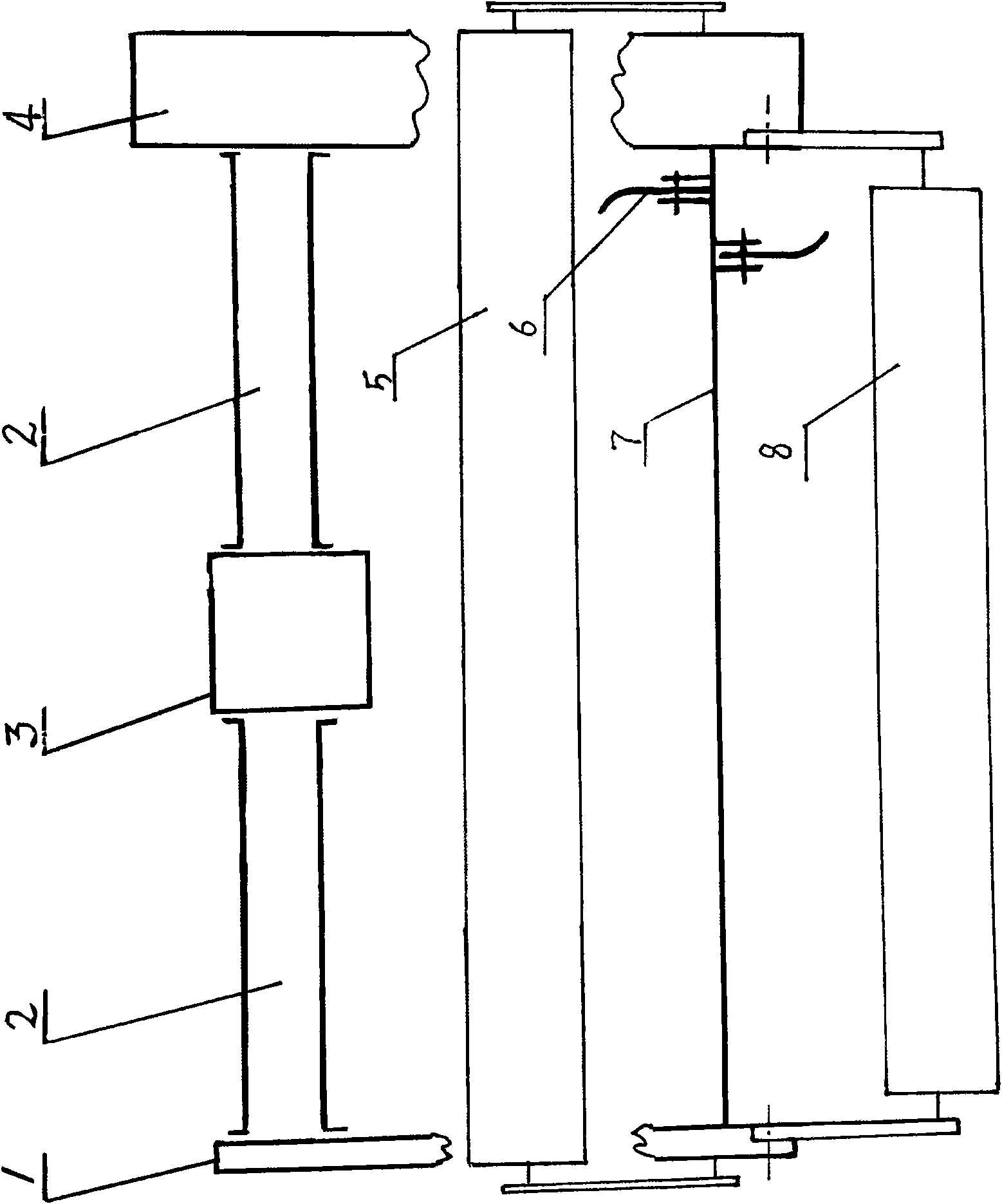
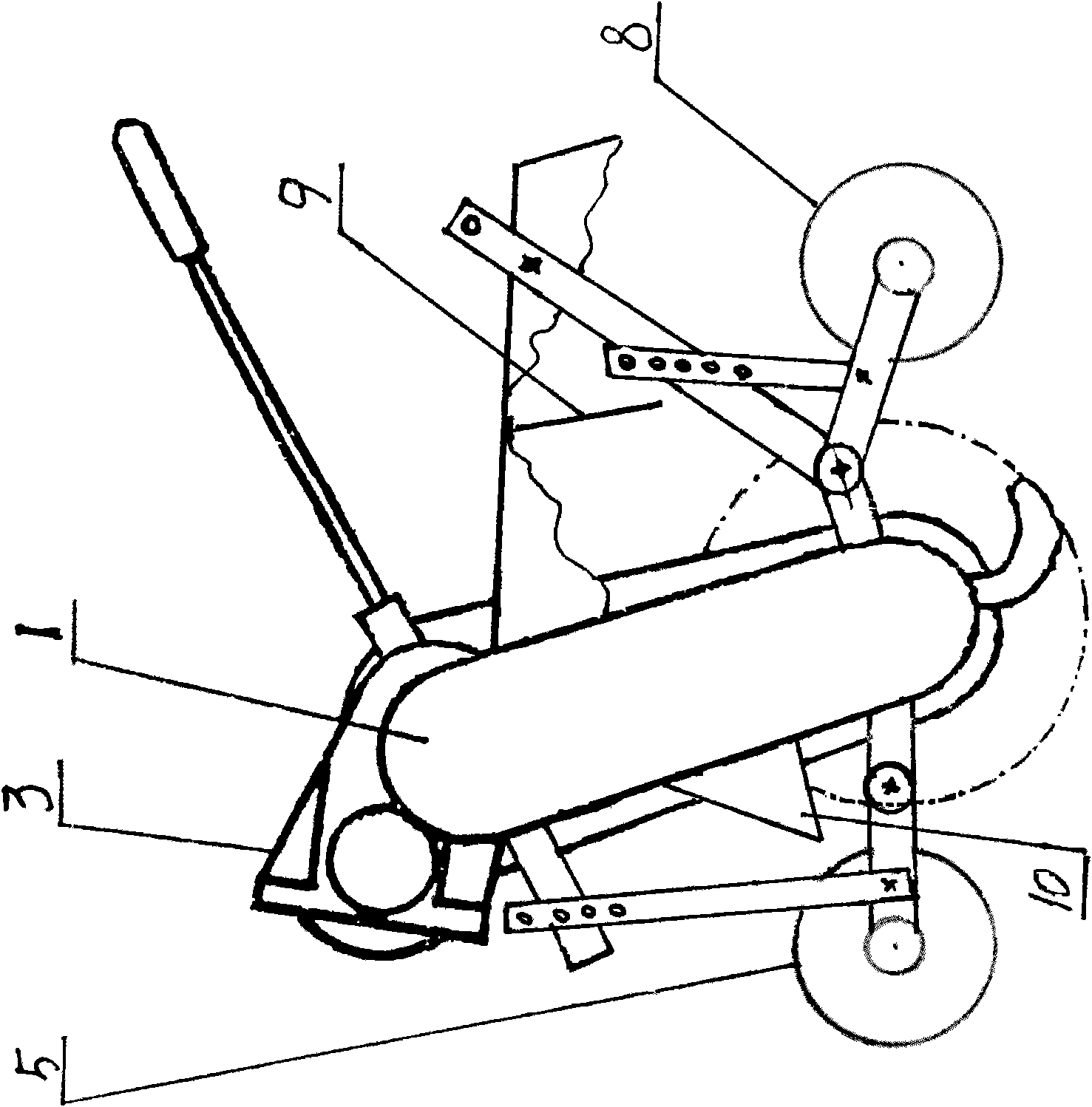
[0010] Such as figure 1 , figure 2 The shown reverse stubble burying rotary tiller comprises a gear box 3 fixed on the housing 2, a power transmission box 4 and a support arm 1, and the bottom of the power transmission box 4 and the support arm 1 supports the two ends of the rotary blade shaft 7. At the end, a pressure roller 5 is arranged directly in front of the rotary blade shaft 7, and a pressure roller 8 is arranged directly behind the rotary blade shaft 7. When the rotary blade shaft 7 reversely rotates and cuts the soil, the blocking The pressure roller 5 blocks the rotary-cut loose soil in front of the rotary tiller shaft 7 and does not turn forward, and the rapidly rotating rotary tiller 6 directs the rotary-cut loose soil and straw directly under the action of the front fender 10 . Throwing to the rear, the stalks are blocked by the fence 9 and fall in front of the fence 9. The center distance between the pressing roller 8 and the rotary tiller shaft 7 is 330-390 m...


PUM


Abstract

The invention discloses a reversal stubble burying rotary cultivator. The rotary cultivator comprises a gear case, a power transmission case and a support arm which are fixed on a shell, wherein the lower parts of the power transmission case and the support arm support both ends of a rotary cultivation cutter shaft, the central front part of the rotary cultivation cutter shaft is provided with a blocking compression roller, the central rear part of the rotary cultivation cutter shaft is provided with a compacting roller, and the blocking compression roller can prevent soil in front of the rotary cultivation cutter shaft and on both sides of the cultivator from piling during the operation, thereby enabling the earth surface planeness to be favorable; in order to improve the stubble buryingeffect, the shaft center distance of the compacting roller and the rotary cultivation cutter shaft ranges from 330 to 390 millimeters, and therefore, the compacting roller can compact in time straw blocked by a fence, and more soil crossing the fence can be scattered on the straw behind the compacting roller; and the straw is compacted firstly and then is covered by the soil, thereby enabling thestubble burying effect to be favorable and the soil consumption to be low, and reducing the depth of rotary cultivation as well as the power consumption.

Description

Technical field [0001] The invention belongs to a plowing machine tool in agricultural machinery, and is a reverse stubble burying rotary tiller Background technique [0002] At present, the reverse stubble burying rotary tiller uses the rotary tiller shaft to reversely cut the soil. Through the function of the fender, the rotary-cut soil is thrown to the rear. The straw is blocked by the fence and falls in front of the fence, and the soil is scattered through the fence. Falling on the straw to achieve the effect of stubble, because the front fender needs a certain distance from the ground, the loose soil in front of the rotary tiller shaft is turned and piled up on both sides of the machine during reverse rotary cutting, forming two numbers A long ridge with a height of one centimeter and a width of more than ten centimeters forms small mounds at the turns and turns. The depth of rotary tillage increases the loose soil and covers the straw, which increases the power consum...

Claims


Application Information

Patent Timeline
IPC IPC(8): A01B49/02A01B33/08
Inventor 王森豹
Owner 王森豹
Learn More