Process and device for preparing thin strips by roller method sputtering forming

A roller method and thin strip technology, applied in the direction of metal rolling, etc., can solve the problems of atomization nozzle inner chamber degeneration, uneven thickness, difficulty in meeting the requirements of nozzles, etc., and achieve the effect of overcoming inhomogeneity and improving atomization efficiency

Active Publication Date: 2011-04-13
BAOSHAN IRON & STEEL CO LTD
View PDF5 Cites 0 Cited by
  • Summary
  • Abstract
  • Description
  • Claims
  • Application Information

AI Technical Summary

Problems solved by technology

[0008]The main disadvantages of this process are:
[0010](2) In the process of preparing slab by spray forming process, if a single nozzle is used, the scale of the slab is very limited; , which increases the complexity of the mechanism, and the iteration problem between the deposition layers of the atomization process
[0011](3) Based on the characteristics of traditional centrifugal spray deposition, it is very suitable for the preparation of tube blanks and rings, but it cannot be implemented for the preparation of slabs
[0014] (1) The interior of the atomizing nozzle is fed with high-speed airflow and high-temperature molten metal at the same time, so it is very severely corroded by the two. Material nozzles will be difficult to meet;
[0015] (2) The high-speed air flow can atomize the metal liquid flow, but at the same time it has a strong cooling effect on the metal particles, and the movement of the metal liquid droplets in the atomizing nozzle During the process, it will be very easy to stick to the edge of the nozzle, and the long-term sticking will cause the denaturation of the inner cavity of the atomizing nozzle, and in severe cases, it will cause blockage;
[0016] (3) The inner cavity of the nozzle with Laval shape will accelerate the air flow, but at the same time, the atomized metal droplets also have a conical distribution , will make the thickness of the metal droplet deposit between the crystallization rollers uneven, resulting in thickness differences inside the sheet
[0017](4) is limited to the form of Laval nozzle, and it is difficult to implement when preparing large-scale thin strips

Method used


Image

  • Process and device for preparing thin strips by roller method sputtering forming
  • Process and device for preparing thin strips by roller method sputtering forming

Examples


Embodiment 1

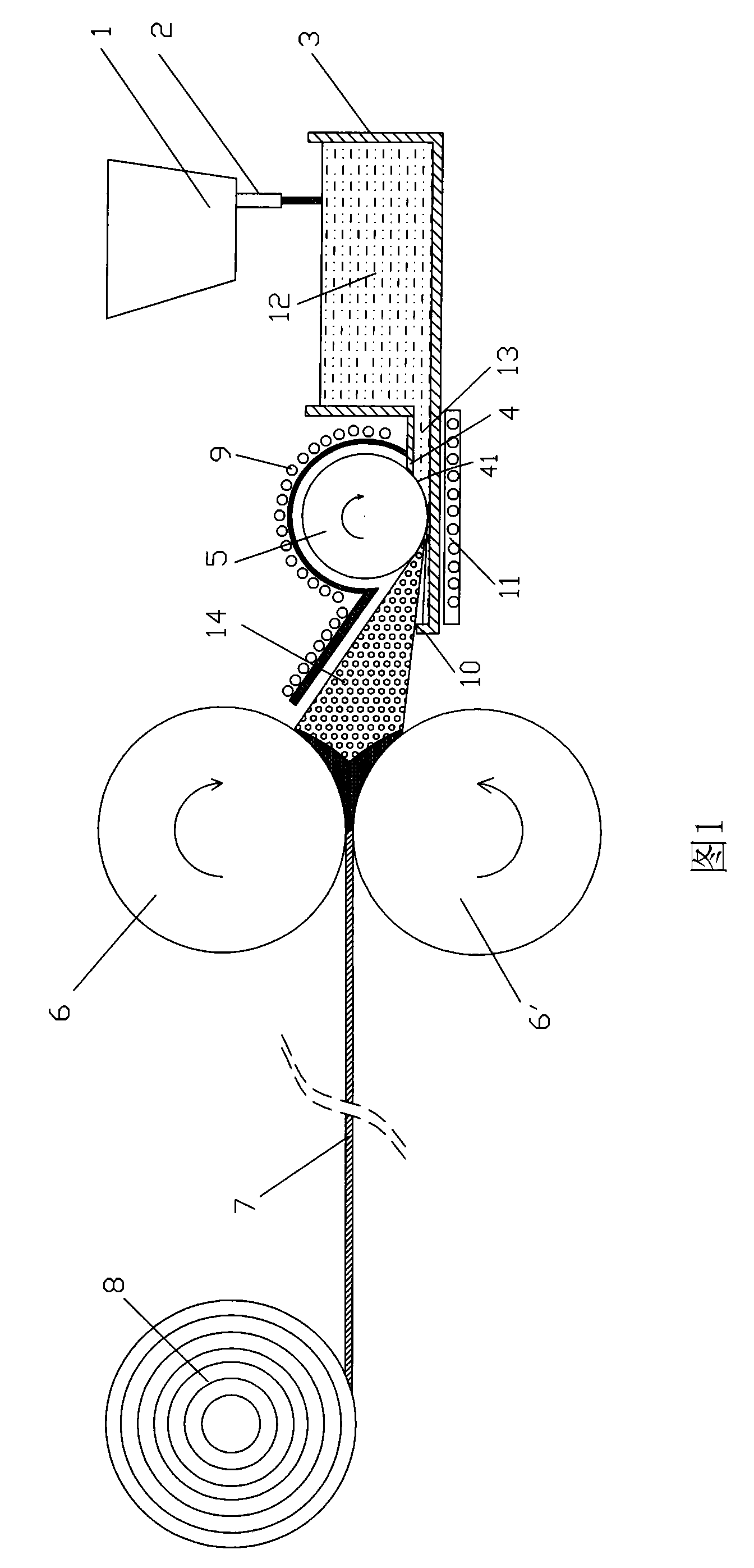
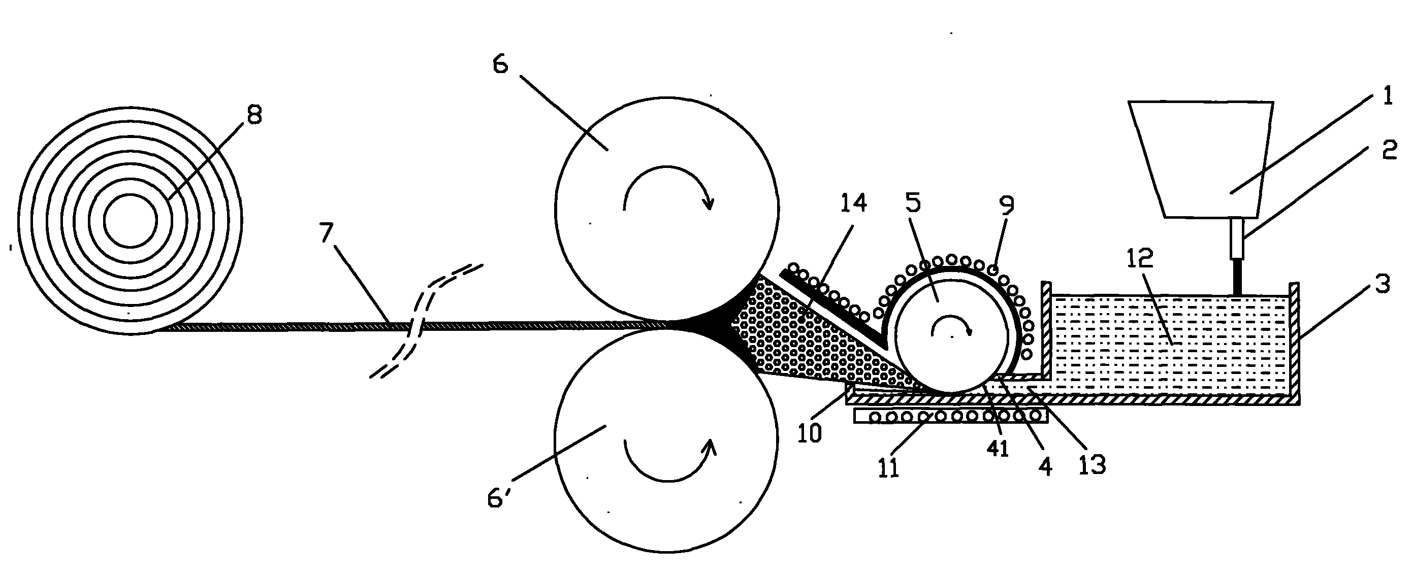
[0045] Pour the molten metal into the ladle, the superheat of the molten metal is kept at about 20°C, the ladle transports the molten steel to the ladle through the nozzle, the liquid level of the ladle is kept at 200mm, and the height of the liquid film prefabricated plate is 20mm. Connected with the drum, the diameter of the drum is 300mm, and there is a heater inside the drum, so that the temperature of the drum is kept lower than the temperature of the molten metal by about 20°C. The gap between the bottom of the drum and the bottom of the prefabricated plate is 5mm wide, and the rotating speed of the drum is 200r / min. The height of the baffle is 30mm, the distance between the cylinder and the crystallization roller is 350mm, the interval between the crystallization rollers is 2mm, the rotating speed of the crystallization roller is 100r / min, the pulling speed of the thin strip is 60m / min, and the temperature of the heater is controlled at It is not advisable to solidify th...

Embodiment 2

[0047] Pour the molten metal into the ladle, the superheat of the molten metal is kept at about 22°C, the ladle transports the molten steel to the ladle through the nozzle, the liquid level of the ladle is kept at 230mm, and the height of the liquid film prefabricated plate is 15mm. Connected to the drum, the diameter of the drum is 260mm, and there is a heater inside the drum to keep the temperature of the drum lower than the molten metal at about 18°C. The gap between the bottom of the drum and the bottom of the prefabricated plate is 6mm wide, and the rotation speed of the drum is 230r / min. The height of the baffle is 25mm, the distance between the drum and the crystallization roller is 380mm, the interval between the crystallization rollers is 2.5mm, the rotation speed of the crystallization roller is 120r / min, the pulling speed of the thin strip is 80m / min, the temperature control of the heater It is preferable that the molten metal solidifies not between the prefabricated...

Embodiment 3

[0049] Pour the molten metal into the ladle, the superheat of the molten metal is kept at about 23°C, the ladle transports the molten steel to the ladle through the nozzle, the liquid level of the ladle is kept at 280mm, and the height of the liquid film prefabricated plate is 12mm. Connected to the drum, the diameter of the drum is 280mm, and there is a heater inside the drum to keep the temperature of the drum lower than the molten metal at about 22°C. The gap between the bottom of the drum and the bottom of the prefabricated plate is 4mm wide, and the rotating speed of the drum is 260r / min. The height of the baffle is 28mm, the distance between the cylinder and the crystallization roller is 400mm, the interval between the crystallization rollers is 4mm, the rotating speed of the crystallization roller is 130r / min, the pulling speed of the thin strip is 100m / min, and the temperature of the heater is controlled at It is not advisable to solidify the molten metal between the pr...


PUM


Abstract

The invention relates to a process for preparing thin strips by roller method sputtering forming, which comprises the following steps that: molten steel flows into a containing ladle through a water gap from a pouring box; the outlet end of the containing ladle is provided with a film prefabricating guide groove for controlling the molten steel to have certain width; the far end on the top surface of the guide groove is provided with an opening and a rotary high temperature roller; a gap for forming the molten steel into a film is reserved between the roller and the bottom of the film prefabricating guide groove; the roller forms the molten steel into a film with small thickness and performs centrifugal atomization at the same time; the high temperature roller rotating at a high speed drives the molten steel at the bottom to perform liquid-film separation, and tiny molten drops are formed through atomization, wherein the molten drops are in Gaussian distribution and are sprayed to the space between two crystallizing rollers which are arranged on the outer side of the film fabricating guide groove and rotate in opposite directions; the crystallizing rollers instantly solidify the molten drops formed through the atomization by the roller, and roll the formed metal deposition layer to form metal thin strips; and the metal thin strips are draught to finally form thin strip coils.

Description

technical field [0001] The invention relates to the field of twin-roll thin strip continuous casting, in particular to a process and a device for preparing thin strip by sputtering forming with a roller method. Background technique [0002] Twin-roll strip continuous casting is a growth process in which two casting rolls rotating in opposite directions are used as crystallizers to directly produce liquid metal into thin strip steel with a thickness of less than 10mm. Compared with the traditional thin strip production process, the modified technology has the advantages of shortening the process flow, saving energy, reducing production costs and improving the mechanical properties of the strip, so the technology is considered to be one of the most promising near net shape continuous casting technologies in the 21st century . [0003] The thin strip continuous casting process is a casting and rolling process that is both related and different from traditional continuous casti...

Claims


Application Information

Patent Timeline
Patent Type & Authority Patents(China)
IPC IPC(8): B22D11/10B22D11/06B21B1/46
Inventor 任三兵樊俊飞乐海荣赵顺利方园
Owner BAOSHAN IRON & STEEL CO LTD
Why Eureka
Try Eureka