Punch forming device of guide grooves of energy-absorbing box of automobile anti-collision rod

An automobile anti-collision bar, stamping and forming technology, applied in the field of metal stamping, can solve the problems of increasing processing cost, reducing processing efficiency, scratches, etc., and achieving the effects of high strength and reliability, reducing production cost and improving work efficiency

Active Publication Date: 2010-02-03
LINGYUN INDAL CORP
View PDF0 Cites 6 Cited by
  • Summary
  • Abstract
  • Description
  • Claims
  • Application Information

AI Technical Summary

Problems solved by technology

During the stamping process, the energy-absorbing box needs to be loaded and unloaded and stretched repeatedly, the energy-absorbing box is easily deformed and scratched, and the process operation has a long turnaround time, which reduces the processing efficiency and increases the processing cost
In addition, another unsolvable process problem is that the mandrel must allow at least one space for the depth of the guide groove for material return, so the mandrel can only be made thin. When the three sides need to avoid the guide groove, the mandrel The maximum thickness and width of the energy-absorbing box can only be about 1 / 2 of the inner cavity size of the energy-absorbing box, and the mandrel generally adopts a cantilever beam structure. Such a mandrel is very easy to break at the place where the guide groove is formed, and the strength cannot be guaranteed.

Method used


Image

  • Punch forming device of guide grooves of energy-absorbing box of automobile anti-collision rod
  • Punch forming device of guide grooves of energy-absorbing box of automobile anti-collision rod
  • Punch forming device of guide grooves of energy-absorbing box of automobile anti-collision rod

Examples


Embodiment Construction

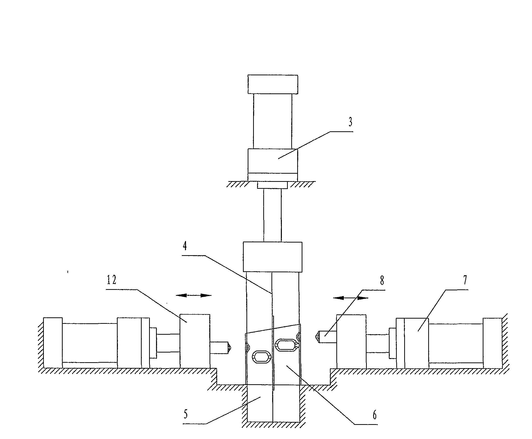
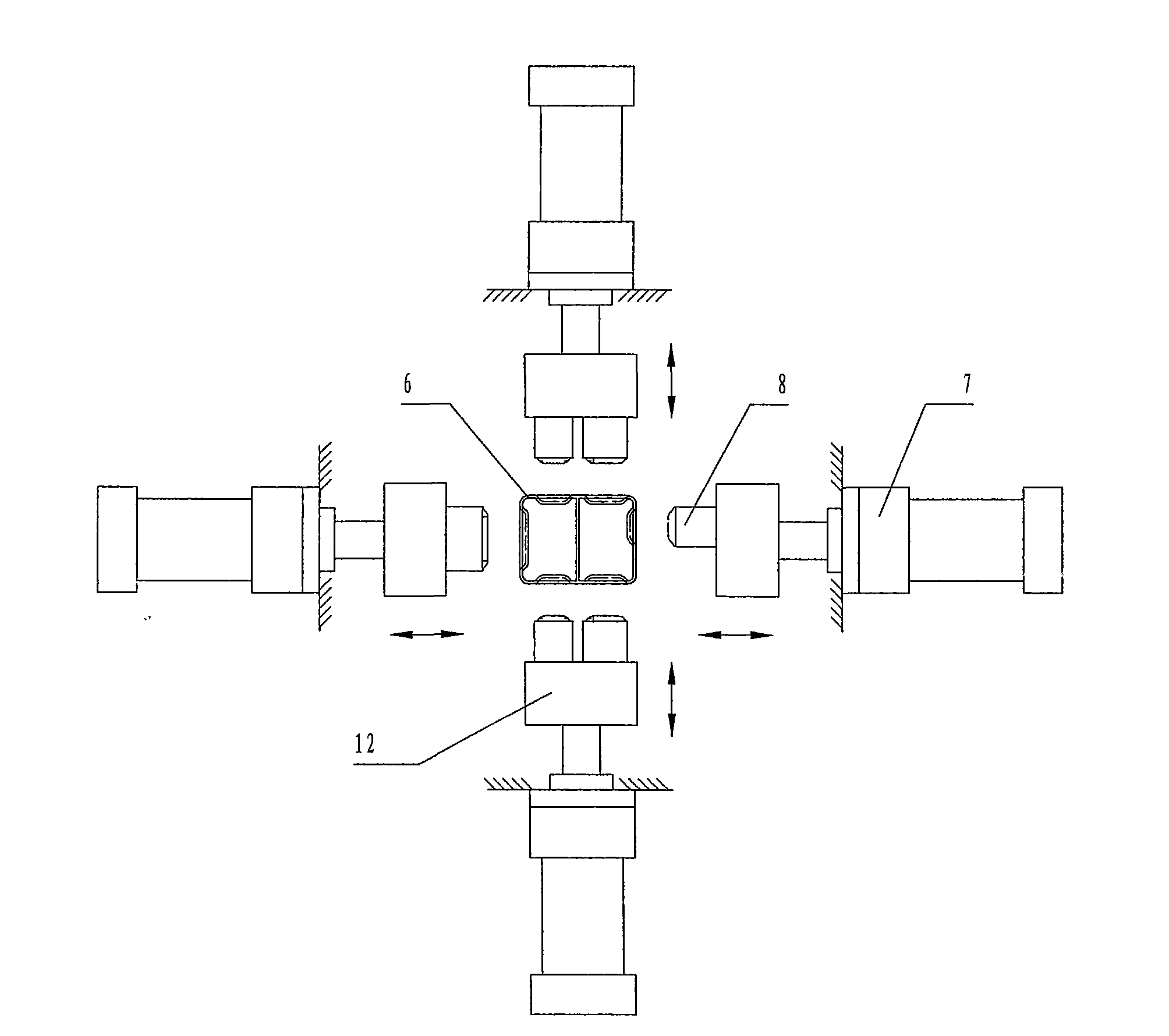
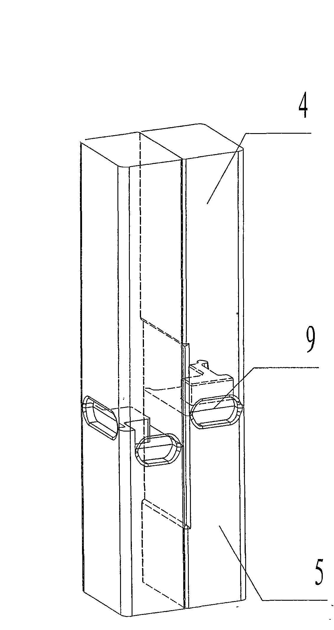
[0018] see Figure 1 ~ Figure 2 , the device includes a mandrel, a mandrel cylinder 3 and a stamping cylinder 7, and the mandrel with a split structure provides the possibility for one-time molding of the guide groove 2 of the energy-absorbing box of the automobile anti-collision bar. In this device, the dies 8 are arranged around, corresponding to the guide grooves 2 on each side of the crash box 6 one by one. The punching die 8 is installed on the slider 12 and reciprocates under the drive of the stamping cylinder 7 . The pressing force of the punching die 8 is very large, which can reach more than ten tons or even higher. Therefore, the core mold must be prevented from being stressed in one direction when the punching die 8 is being pressed in. The device connects the stamping oil cylinders 7 located on opposite sides of the mandrel to the same oil circuit, so that the pressure on both sides is consistent, which can ensure the synchronization of the punching dies 8 on both...


PUM


Abstract

The invention discloses a punch forming device of guide grooves of an energy-absorbing box of an automobile anti-collision rod, which is used for solving the forming problem of the guide grooves. Thetechnical scheme is as follows: the punch forming device comprises a core die, a core die oil cylinder and punching oil cylinders, wherein the shape of the core die is matched with the shape of an inner cavity of the energy-absorbing box and is combined by an upper part and a lower part which are respectively a static core die positioned therebelow and a movable core die positioned thereabove; theinterface of the upper part and the lower part is a folding surface and divides concave dies corresponding to all guide grooves into an upper part and a lower part; the core die oil cylinder is positioned above the core die and a piston rod thereof drives the movable core die; the punch oil cylinders are four and respectively correspond to the guide grooves on the four surfaces of the energy-absorbing box; and each punching oil cylinder drives a punching die which is matched with the corresponding punching die. Compared with the traditional punching device, the punch forming device has high punching efficiency and simple operation, not only guarantees the quality of the energy-absorbing box, but also reduces the production cost.

Description

technical field [0001] The invention relates to a device for stamping guide grooves on an energy-absorbing box of an automobile anti-collision bar, belonging to the technical field of metal stamping. Background technique [0002] The automobile anti-collision bar energy-absorbing box is a part of the car bumper. On the one hand, it provides support and fixes the bumper on the car body. Absorbs energy from impact. figure 1 It is a commonly used energy-absorbing box with a "day"-shaped cross-section and a closed cavity structure. Its four walls are covered with concave guide grooves at different positions, which are used to reduce the strength of the position of the guide groove and make the absorber When the energy box collapses, it can first start to collapse from the guide groove according to the predetermined designed route. [0003] The four walls of the energy-absorbing box are designed with different numbers of guide grooves. When the existing punching device is used ...

Claims


Application Information

Patent Timeline
Patent Type & Authority Applications(China)
IPC IPC(8): B21D28/02B21D28/14
Inventor 刘东海韩振宇
Owner LINGYUN INDAL CORP
Why Eureka
Try Eureka