Clamping mechanism

A technology of clamping mechanism and clamping block, which is applied in the direction of chuck, manipulator, drilling equipment, etc., can solve the problems of narrow pipe diameter range, insufficient clamping force, insufficient strength, etc., and achieve improved stress state, simple structure, The effect of small bending moment

Active Publication Date: 2010-02-03
SICHUAN HONGHUA PETROLEUM EQUIP
View PDF0 Cites 44 Cited by
  • Summary
  • Abstract
  • Description
  • Claims
  • Application Information

AI Technical Summary

Problems solved by technology

However, this kind of clamping mechanism has the following problems in use: since the clamping block with a curved surface is opened and then closed, the clamping is realized by surrounding the pipe string with the curved surface, and the curved surface of the clamping block is fixed, so it can only clamp When holding a string with a smaller size range, when the clamping range is exceeded, the entire clamping mechanism can only be replaced, which is quite troublesome
This kind of clamping method also has problems that need to be improved: the curved surface of the clamping block surrounds the pipe string, and the curved surface is suitable for a narrow range of pipe diameters, and the same clamping mechanism cannot clamp pipe strings within a larger outer diameter range, such as The above-mentioned 3.5-9.75 inches (88.9mm-247.7mm); since the clamping block rotates around the fulcrum at the rear, when the clamping block is opened and closed, its front part has a larger range of motion in the width direction. When the small-diameter pipe string is used, the clamping block easily interferes with the adjacent pipe string to be clamped; the rotation fulcrum of the clamping block is at the rear, and the cantilever of the clamping block is long, which easily causes insufficient clamping force , not strong enough

Method used


Image

  • Clamping mechanism
  • Clamping mechanism
  • Clamping mechanism

Examples


Embodiment Construction

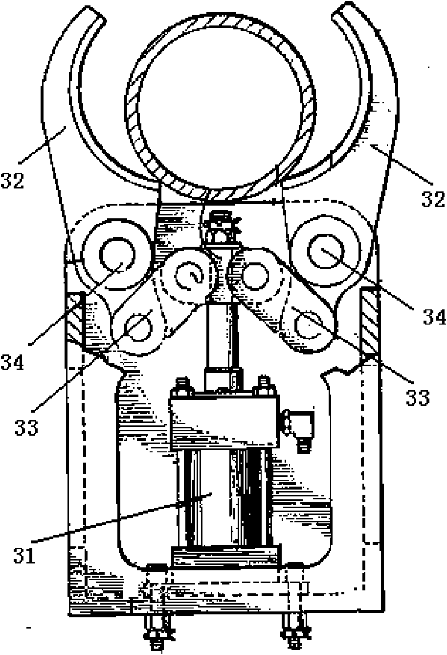
[0032] Below in conjunction with accompanying drawing and embodiment the present invention will be further described:

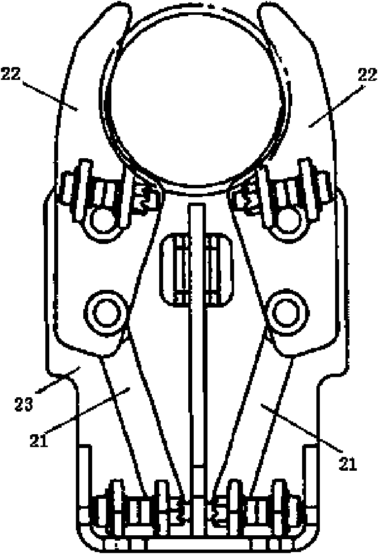
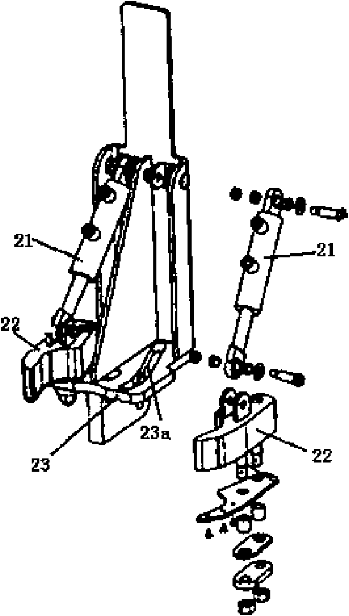
[0033] Such as Figure 4 to Figure 6 As shown, a clamping mechanism mainly consists of a housing 1, an oil cylinder 2 clamping block 3, a connecting plate 4, a fixed block 5, a first tooth plate 6, a second tooth plate 7, a pulley 8 and pins. Wherein, the housing 1 is welded by two cover plates 11 on the upper and lower ends, two side plates 12 on the left and right sides, and a bottom plate 13. The two cover plates 11 and the two side plates 12 are symmetrically arranged respectively, and the two side plates 12 are shorter than The two cover plates 11 form openings on both sides of the front portion of the two cover plates 11, the bottom plate 13 closes the rear end of the housing 1, and two ear plates 14 with hinged holes are fixed on the outer surface of the bottom plate 13. Housing 1 is equipped with an oil cylinder 2, the cylinder barrel of oil cylinder...


PUM


Abstract

The invention discloses a clamping mechanism which comprises a shell and an oil cylinder installed in the shell, wherein clamping blocks are distributed in the front part of the shell in bilateral symmetry; and the inner side surfaces of the front half parts of the clamping blocks are inner concave surfaces. The clamping mechanism is characterized in that a cylinder barrel of the oil cylinder is centered at the rear part of the shell; the front end of a piston rod of the oil cylinder is articulated with a connecting plate; the left part and the right part of the connecting plate are respectively articulated with the rear ends of the clamping blocks; the front part of at least one cover plate of the shell is symmetrically provided with guide grooves left and right; guide pins are arranged in the middle parts of the two clamping blocks and inserted into the guide grooves; fixed blocks are clamped and fixed in the middle parts of the front ends of the two cover plates, and the normal lineof the surfaces of the front parts of the inner concave surfaces of the two clamping blocks are inclined to the directions of the fixed blocks. The invention has simple structure, high strength and large clamping force and can be suitable for different pipe columns with the external diameter range of 3.5-9.75 inches without replacing the clamping mechanism, and the clamping mechanism can not interfere with the adjacent pipe column during working.

Description

technical field [0001] The invention belongs to automatic tools of oil drilling equipment, in particular to a clamping mechanism of a vertical root discharge manipulator. Background technique [0002] The automation of drill pipe discharge and the field pipe transportation system are one of the key technologies for drilling rig automation. The stand discharge manipulator is an important component of the drill pipe discharge automation mechanism and the site discharge pipe transportation system. Refer to the specified position on the beam frame; 2) When running in, send the vertical root at the specified position on the finger beam frame to the centerline of the wellbore; 3) When pulling out, send the vertical root from the centerline of the wellbore to the finger frame specified location on the . [0003] The working conditions of the vertical root discharge manipulator make the clamping mechanism of the vertical root discharge manipulator very different from that of other...

Claims


Application Information

Patent Timeline
Patent Type & Authority Applications(China)
IPC IPC(8): B25J15/00E21B19/14
Inventor 姚宇翔陈俊刘宣国
Owner SICHUAN HONGHUA PETROLEUM EQUIP
Why Eureka
Try Eureka