Method for replacing rotating furnace

A converter and furnace body technology, applied in the field of converter replacement, can solve the problems of difficulty in controlling the quality of new converter assembly, long working hours, and high-altitude operations, so as to avoid operating procedures and high-altitude operations, good quality and good construction conditions Effect

Inactive Publication Date: 2011-04-06
CHINA FIRST METALLURGICAL GROUP
View PDF0 Cites 0 Cited by
  • Summary
  • Abstract
  • Description
  • Claims
  • Application Information

AI Technical Summary

Problems solved by technology

The disadvantages of this traditional process are: cumbersome procedures, many high-altitude operations, many hidden dangers, difficulty in controlling the assembly quality of the new converter, and long working hours

Method used


Image

  • Method for replacing rotating furnace
  • Method for replacing rotating furnace
  • Method for replacing rotating furnace

Examples


Embodiment 1

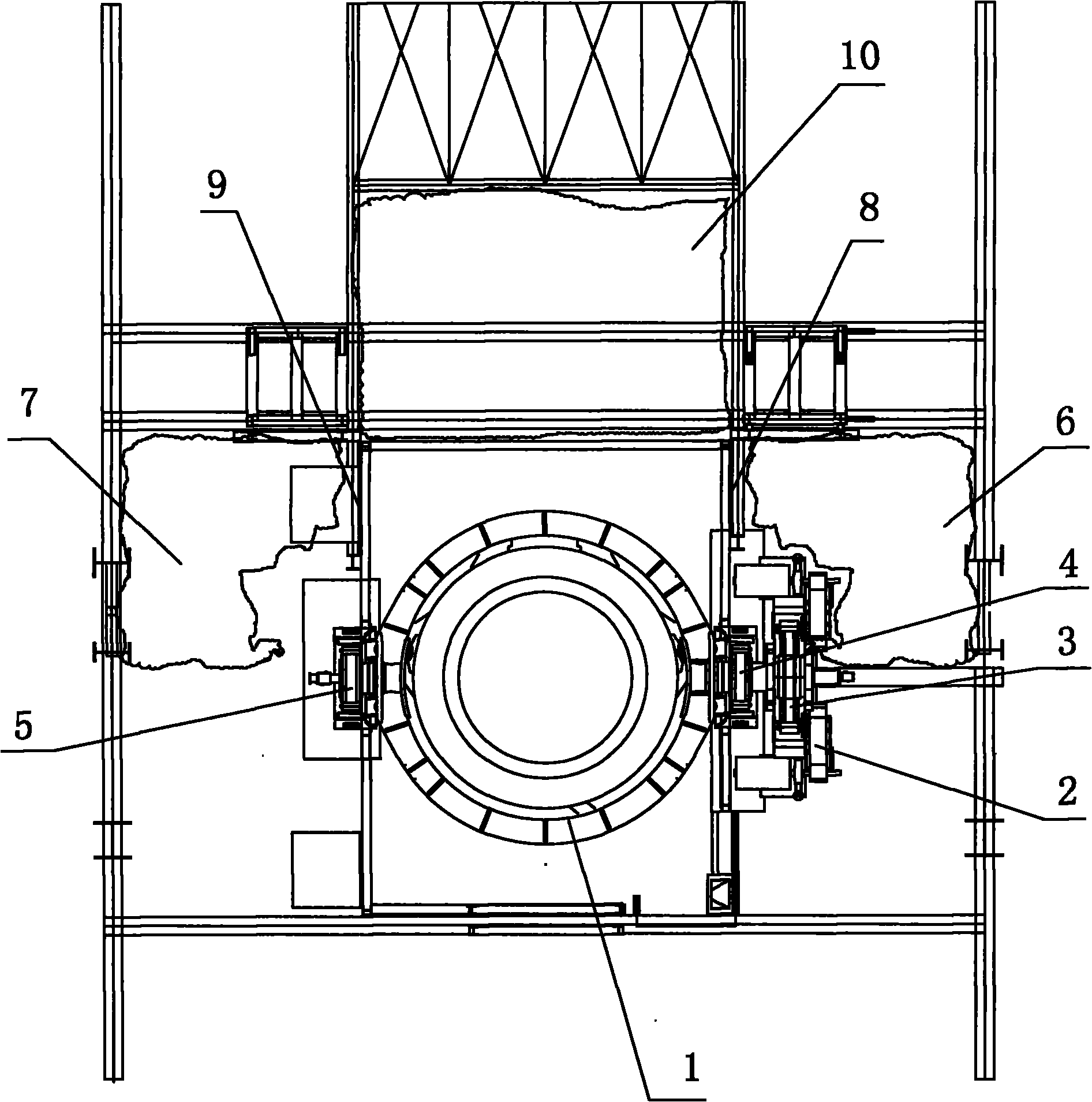
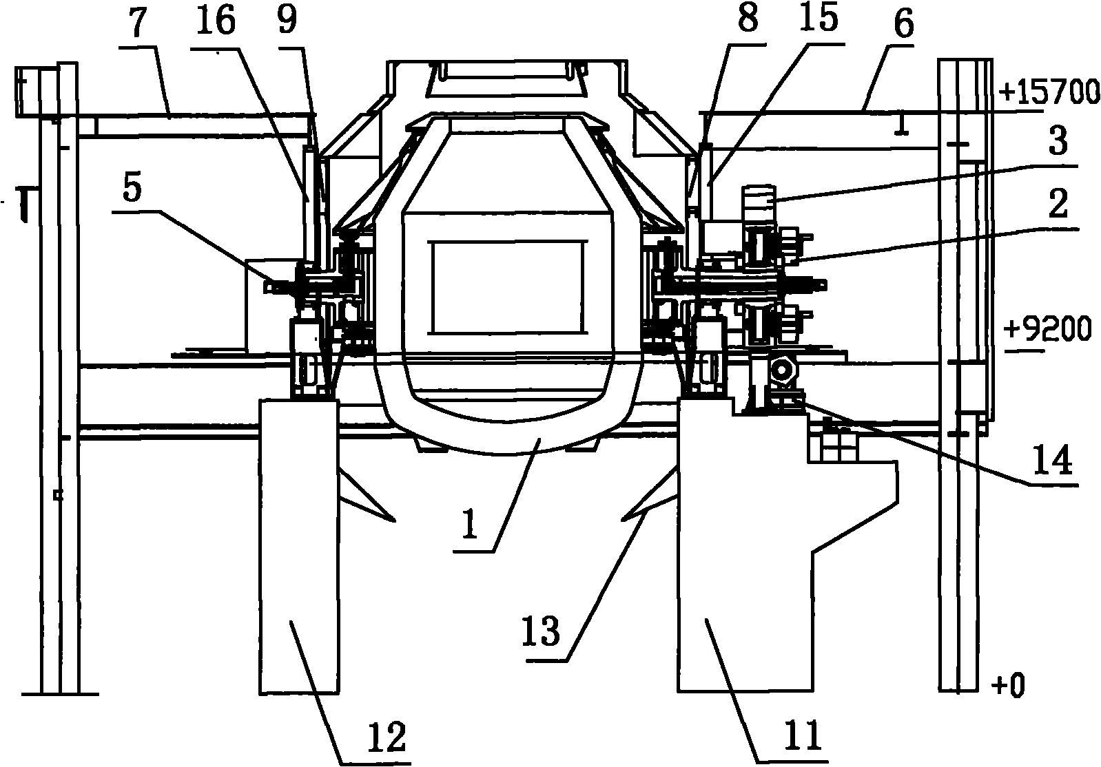
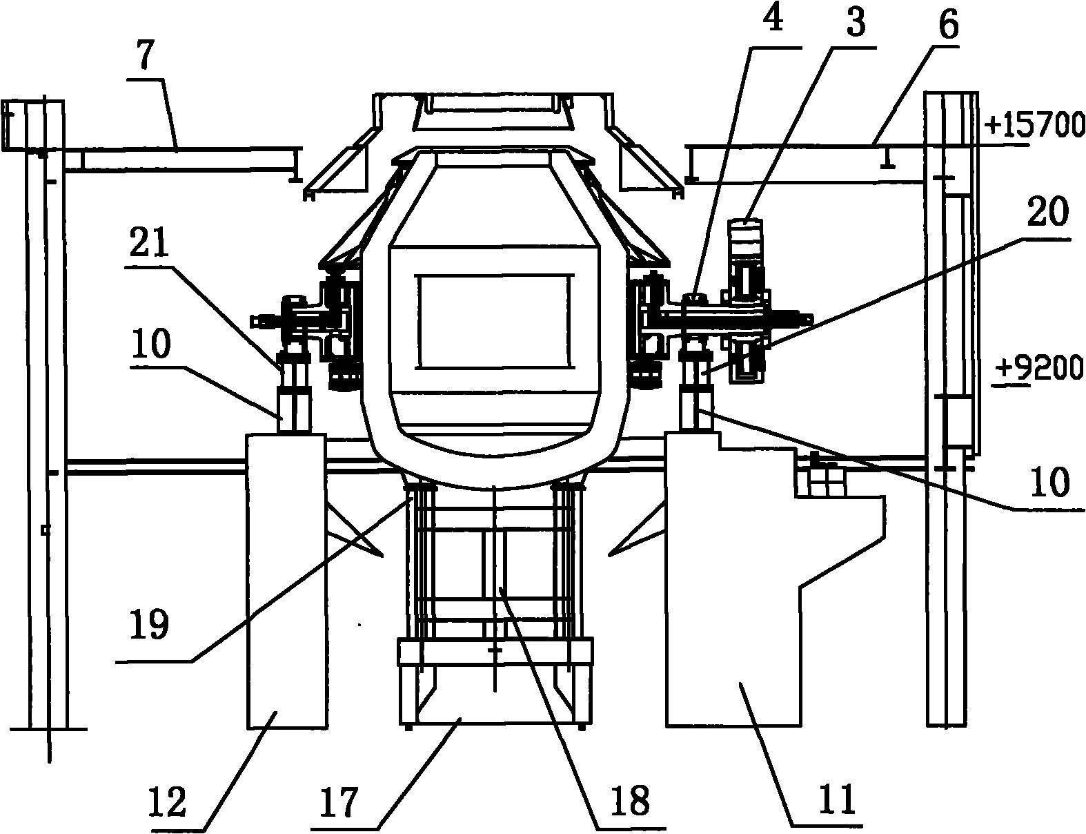
[0023] Such as figure 1 , figure 2 , image 3 , Figure 4 As shown, the method for replacing the converter includes the following steps:

[0024] 1) Before the old converter is dismantled, assemble the new converter in the span where the crane used for hoisting after the old converter is dismantled {furnace body, support ring, skirt plate, furnace mouth flange, bearing seat, dumping device (secondary reducer ) etc. for overall assembly}, leaving the primary reducer and torsion bar of the new converter to be installed; these tasks need to be completed in the preparatory stage before the start of maintenance. After the position is completed, the assembly direction should be the same as the installation direction of the new converter, because the direction cannot be rotated when the two cranes are lifted;

[0025] 2) Fix the carrier platform 18 on the ladle car 17, and fix four hydraulic jacks 19 (each 200t) on the carrier platform 18; then run the ladle car 17 to the bottom...


PUM


Abstract

The invention relates to a method for replacing a rotating furnace, which is characterized by comprising the following steps: 1) carrying out assembling to a new rotating furnace in a span in which travelling cranes for lifting are located; 2) fixing a carrying stand on a ladle car, and fixedly arranging four hydraulic jacks on the carrying stand; then running the ladle car to the lower part of the furnace body of the old rotating furnace, lifting the four hydraulic jacks, supporting four supporting legs at the bottom part of the furnace body of the old rotating furnace on the corresponding four hydraulic jacks; 3) removing a torsion rod and a primary speed reducer of the old rotating furnace and removing the barriers in the span in which the travelling cranes are located and at the frontof running for removing the old rotating furnace; 4) running the ladle car and leading the old rotating furnace to separate from the original installing position; and 5) moving two travelling cranes and lifting a new rotating furnace to the installing position; and installing the primary speed reducer and the torsion rod of the new rotating furnace. The method is characterized by having fast construction speed, saving cost and reducing potential safety hazard.

Description

technical field [0001] The invention relates to a method for replacing a converter. Background technique [0002] With the continuous development of the domestic metallurgical industry, the trend of the iron and steel industry becoming bigger and stronger is irreversible. With the advancement of iron and steel smelting technology, many steel mills need to carry out technological innovation and replacement of existing equipment. For the replacement of the metallurgical converter, the traditional process is to dismantle the old converter body, support ring, bearing seat and tilting device, etc., and then hoist them one by one. The new converter also needs high-altitude assembly. The disadvantages of this traditional process are: cumbersome procedures, many high-altitude operations, many hidden dangers, difficulty in controlling the assembly quality of the new converter, and long working hours. [0003] In the increasingly fierce market competition, saving time means creatin...

Claims


Application Information

Patent Timeline
Patent Type & Authority Patents(China)
IPC IPC(8): C21C5/28
Inventor 刘金平侯新波周勇王胜明王汉民王良玉殷波
Owner CHINA FIRST METALLURGICAL GROUP
Why Eureka
Try Eureka