Lamp and lighting equipment

A technology for lighting devices and sockets, applied to lighting devices, lighting and heating equipment, parts of lighting devices, etc., to achieve the effects of ensuring assembly, easy insulation, and ease of use

Inactive Publication Date: 2011-08-31
TOSHIBA LIGHTING & TECH CORP
View PDF1 Cites 1 Cited by
  • Summary
  • Abstract
  • Description
  • Claims
  • Application Information

AI Technical Summary

Problems solved by technology

[0004]However, this type of bulb-type lamp has the following problems: the connector frame blocks the light emitted from the LED, and the uniformity of light distribution may decrease

Method used


Image

  • Lamp and lighting equipment
  • Lamp and lighting equipment
  • Lamp and lighting equipment

Examples


Embodiment Construction

[0079] Hereinafter, an embodiment of the present invention will be described with reference to the drawings.

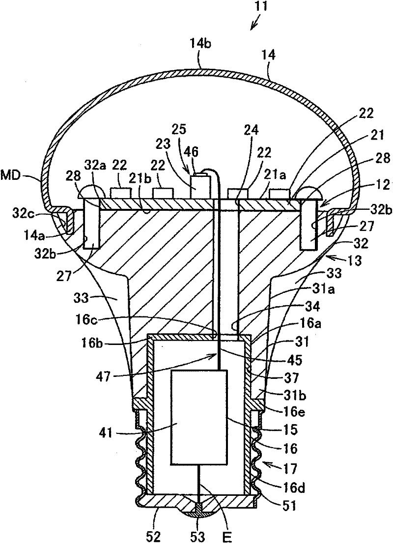
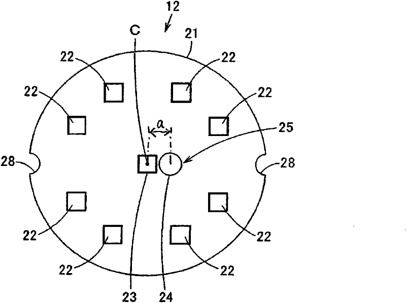
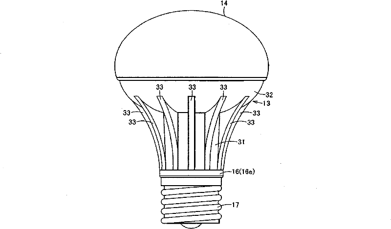
[0080] Figure 1 to Figure 4 The table shows the first embodiment, figure 1 is a longitudinal sectional view of the lamp device, figure 2 is a plan view of the element substrate of the lamp device, image 3 is the side view of the light fixture, Figure 4 It is an explanatory drawing schematically showing the state in which the lighting fixture to which the said lamp apparatus was attached was installed on the ceiling surface.

[0081] exist figure 1 and image 3 Among them, 11 represents a bulb-type lamp as a lamp device, that is, a bulb-type LED lamp. The structure of this bulb-type LED lamp 11 is as follows: an LED substrate 12 as an element substrate is mounted on one end side of a radiator 13, and a lampshade 14 covers the LED substrate 12. Installed on one end side of this radiator 13, on the other end side of this radiator 13, is installed an insulatin...


PUM


Abstract

The present invention relates to a lamp and a lighting equipment. A plurality of LEDs are provided to an outer edge side of a center position of one main surface of an LED substrate main body in a deviated manner respectively. The wiring part including the connector receiving part and the wiring hole are provided at a position that overlaps the center position of the one main surface side of the LED substrate main body. Since the power feeding part is inserted into the wiring hole, the connection part and the connector receiving part can be easily connected and therefore it becomes possible to ensure ease in assembly. Since the connector receiving part is kept away from each of the LEDs with substantially equal distance so that emitted light is hardly blocked, decrease in uniformity of light distribution can be suppressed.

Description

technical field [0001] The present invention relates to a lamp device and a lighting fixture including an element substrate on which a plurality of light emitting elements are arranged. [0002] Background technique [0003] Previously, with regard to a lamp device using a light emitting diode (Light Emitting Diode, LED) as a light emitting element, that is, an LED lamp (lamp), for example, as disclosed in Japanese Patent Application Laid-Open No. 2006-313718, uniformly installed An LED substrate, which is an element substrate of the LED, is mounted on one end side of the heat sink, and a globe is mounted on one end side of the heat sink to cover the LED substrate. Further, a housing case containing a lighting device for controlling lighting of the LED substrate is inserted into the other end side of the heat dissipation portion, and a socket is attached to the housing case on the opposite side of the heat dissipation portion. [0004] When connecting the lighting device to...

Claims


Application Information

Patent Timeline
Patent Type & Authority Patents(China)
IPC IPC(8): F21S2/00F21V19/00F21V23/00F21V23/06F21V29/00F21Y101/02
CPCF21K9/1355F21Y2101/02F21V23/006F21V23/002F21K9/00F21V19/0055F21V3/02F21K9/135F21V17/101F21K9/232F21K9/238F21Y2115/10
Inventor 田中敏也久安武志大泽滋
Owner TOSHIBA LIGHTING & TECH CORP
Why Eureka
Try Eureka