Toner container and image forming device
A technology of toner container and imaging equipment, which is applied in the direction of equipment, electrical recording process equipment using charge patterns, and electrical recording technology, and can solve the problem of affecting the layout, inability to increase the toner amount of the toner storage container, etc. question
- Summary
- Abstract
- Description
- Claims
- Application Information
AI Technical Summary
Problems solved by technology
Method used
Image

Examples
no. 1 approach
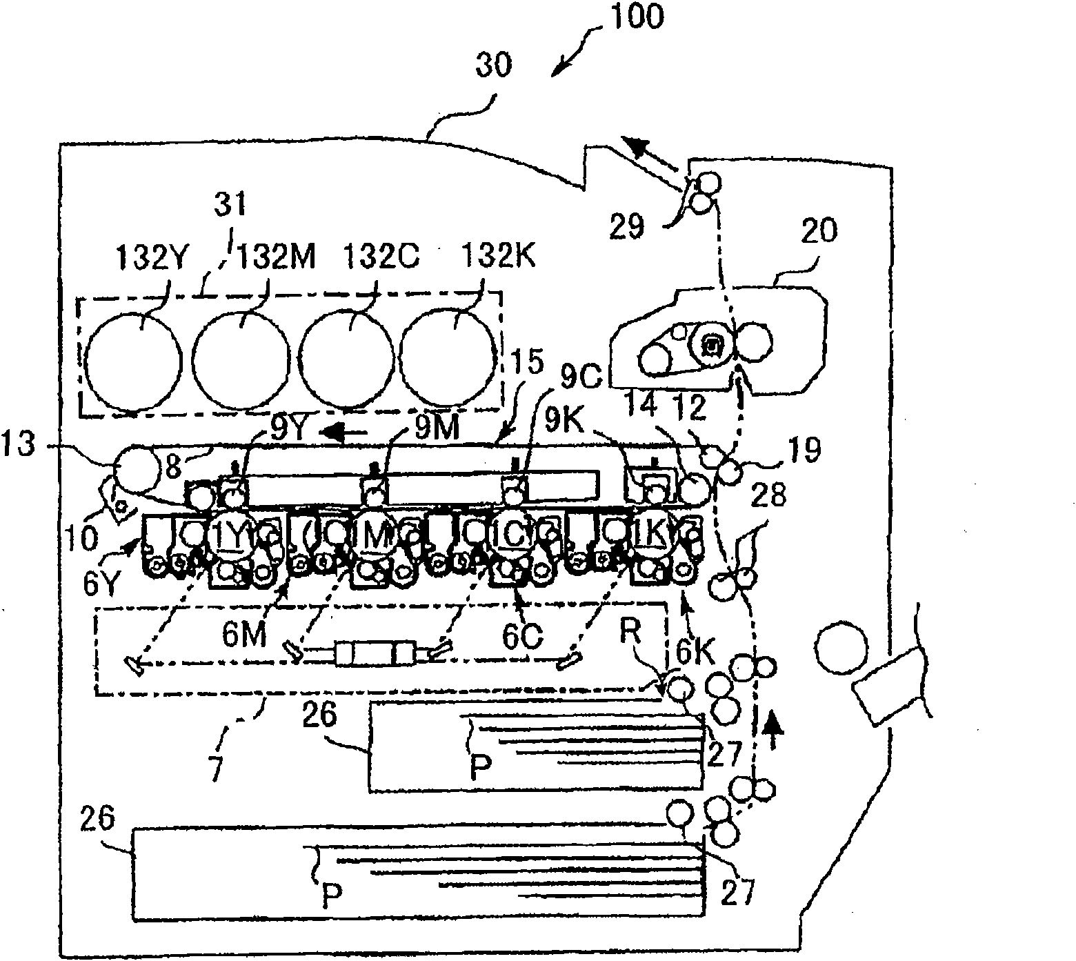
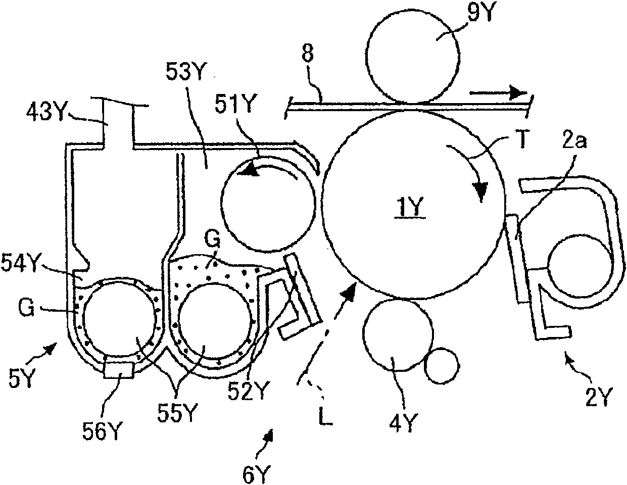
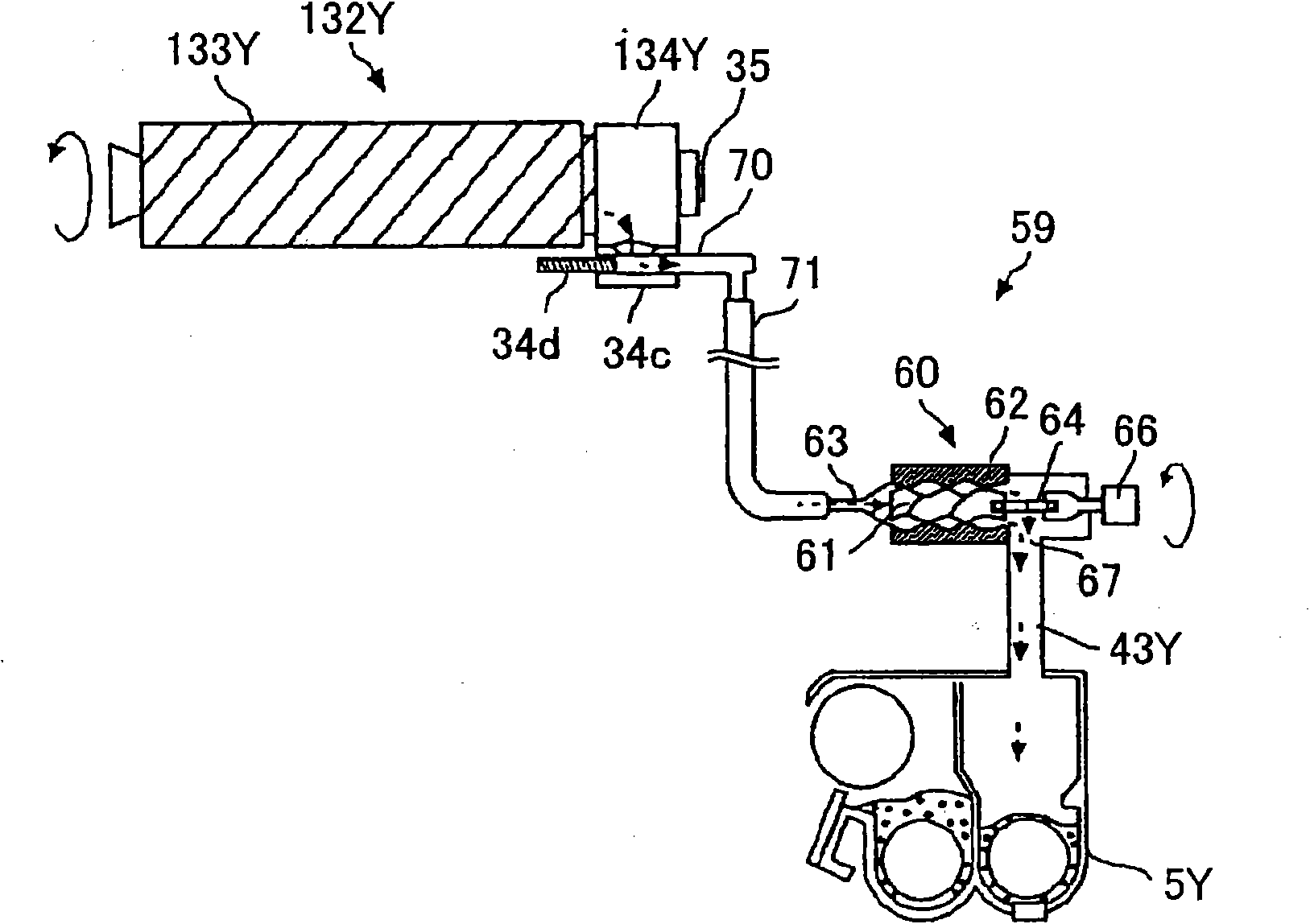
[0245] The following will refer to Figures 1 to 14 The first embodiment of the present invention will be described in detail. First refer to Figure 1 to Figure 4 The structure and operation of the entire imaging device are explained. figure 1 is an overall schematic diagram of a printer as an image forming device, figure 2 is a cross-sectional view of an imaging unit of an imaging device, image 3 a schematic diagram of its toner supply path, and Figure 4 It is a perspective view of a part of the toner container holder.
[0246] Such as figure 1 As shown, four toner containers 132Y, 132M, 132C, and 132K correspond to different colors (yellow, magenta, cyan, and black), and are detachably (replaceably) arranged on the main body of the image forming apparatus 100 in the toner container holder 31 in the side. An intermediate transfer unit 15 is provided in the lower side of the toner container holder 31 . Image forming units 6Y, 6M, 6C, and 6K corresponding to differe...
no. 2 approach
[0331] The following will refer to Figure 15 to Figure 1 8. The second embodiment of the present invention will be described in detail. Figure 15 is a sectional view of the head side of the toner container according to the second embodiment, which is different from that according to the first embodiment Figure 6 corresponding to the sectional view.
[0332] refer to Figure 15 , The toner container 232Y according to the second embodiment is different from the first embodiment in that a compression spring 34f as a biasing member is provided in the held portion 234Y. More specifically, a compression spring 34f (biasing member) for biasing the plugging member 34d in a direction to close the toner outlet B is provided on the right-hand side of the plugging member 34d. The ID chip 35 as an electronic component (storage unit) is configured to be in direct contact with the communication circuit 74 of the device main body. A protruding portion as an erection prevention unit is ...
no. 3 approach
[0349] The following will refer to Figure 19 A third embodiment of the present invention will be described in detail. Figure 19 is a sectional view of a toner container according to a third embodiment. The toner container according to the third embodiment differs from the embodiment in which the container main body rotates to convey the toner contained therein to the opening A in that the container main body 333Y having the held portion 334Y is in a non-rotating manner It is held by the toner container holder 31 , and a coil 181Y as a conveying member is provided in the toner container.
[0350] Such as Figure 19 As shown, the toner container 332Y mainly includes a container main body 333Y and a held portion 334Y. An opening A is provided in the head of the container main body 333Y, and a gear 33c is rotatably provided around the outer periphery of the opening A. As shown in FIG. The gear 33c meshes with the driving gear of the apparatus main body 100 to rotate the coil...
PUM
 Abstract
Description
Claims
Application Information