Film yarn covering and wrapping machine

A wrapping machine and wire wrapping technology, which is applied to electrical components, circuits, and conductor/cable insulation, etc., can solve the problems of limited use of coated wires, difficult drying, slow wire travel, etc., to improve the drying effect. , The effect of ensuring product quality and improving production efficiency

Inactive Publication Date: 2010-02-03
CHANGSHU HAOWEIFU MACHINERY MFG
View PDF1 Cites 6 Cited by
  • Summary
  • Abstract
  • Description
  • Claims
  • Application Information

AI Technical Summary

Problems solved by technology

The current solution is to control the speed of travel of the wire, but the facts show that even if the speed of the wire is slow again, it can only be obtained by the third dipping tank 4c after being wrapped by the second insulating ribbon wrapping device 5b. The drying effect of the third impregnated layer after impregnation, and for the drying of the first impregnated layer after being wrapped by the insulating film wrapping device 2 and impregnated by the first dipping tank 4a and by the first insulating ribbon wrapping device 5a The drying of the second impregnated layer after wrapping and impregnated by the second impregnated tank 4a does not significantly improve the effect, that is to say, it is difficult for the aforementioned first and second impregnated layers to be well dried by the drying device 7. drying
Needless to say, the bonding strength between the insulating ribbon and the insulating film and between the insulating ribbon wrapped for the first time and the insulating ribbon wrapped for the second time will not show a satisfactory degree, so that the covering wire Expansion of uses is constrained

Method used


Image

  • Film yarn covering and wrapping machine
  • Film yarn covering and wrapping machine

Examples


Embodiment Construction

[0018] In order to enable the examiners of the patent office, especially the public, to understand the technical essence and beneficial effects of the present invention more clearly, the applicant will describe in detail below in conjunction with the accompanying drawings in the form of embodiments, but none of the descriptions of the embodiments is a description of the present invention. Restriction of the inventive solution, any equivalent transformation made according to the concept of the present invention which is only in form but not in substance shall be regarded as the scope of the technical solution of the present invention.

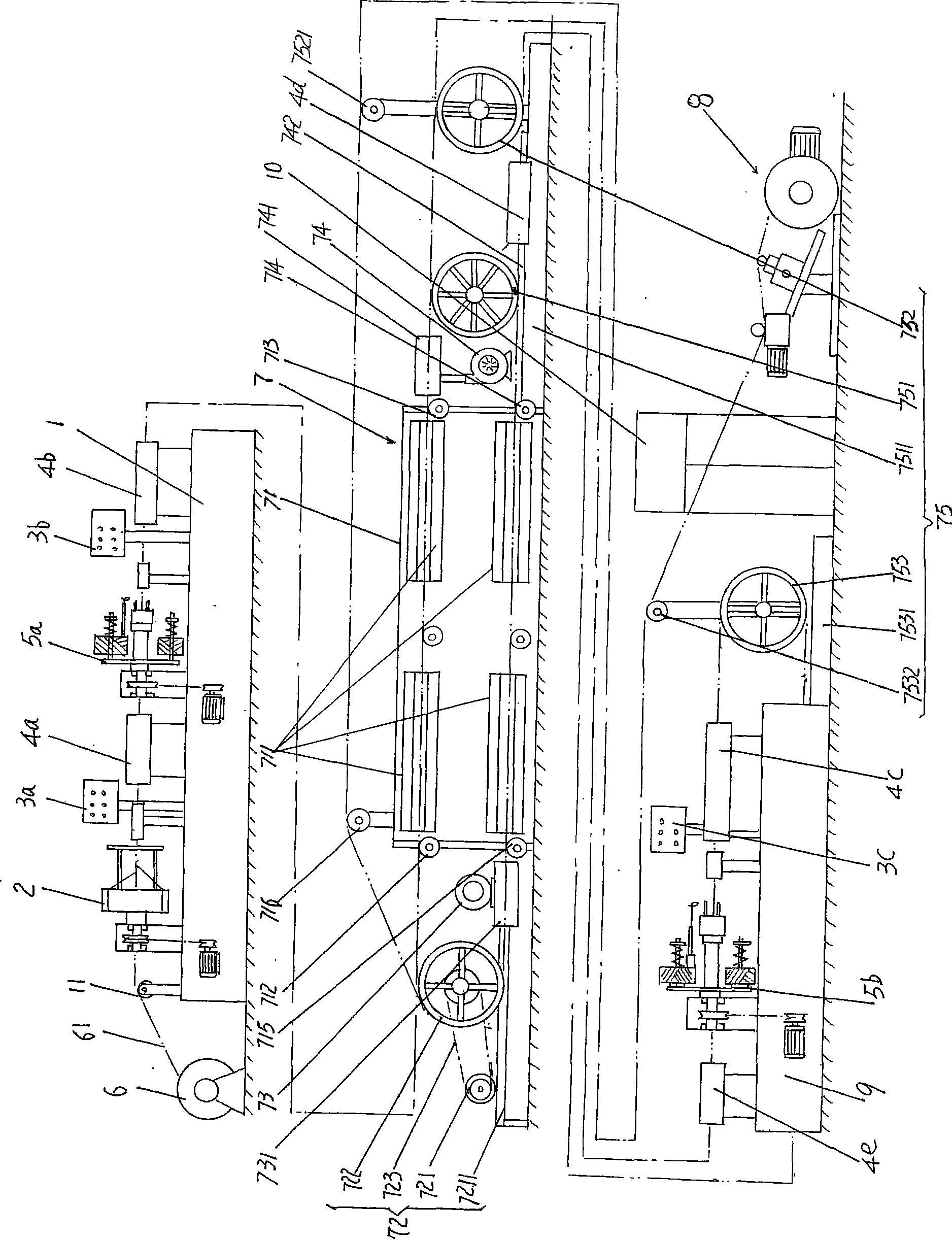
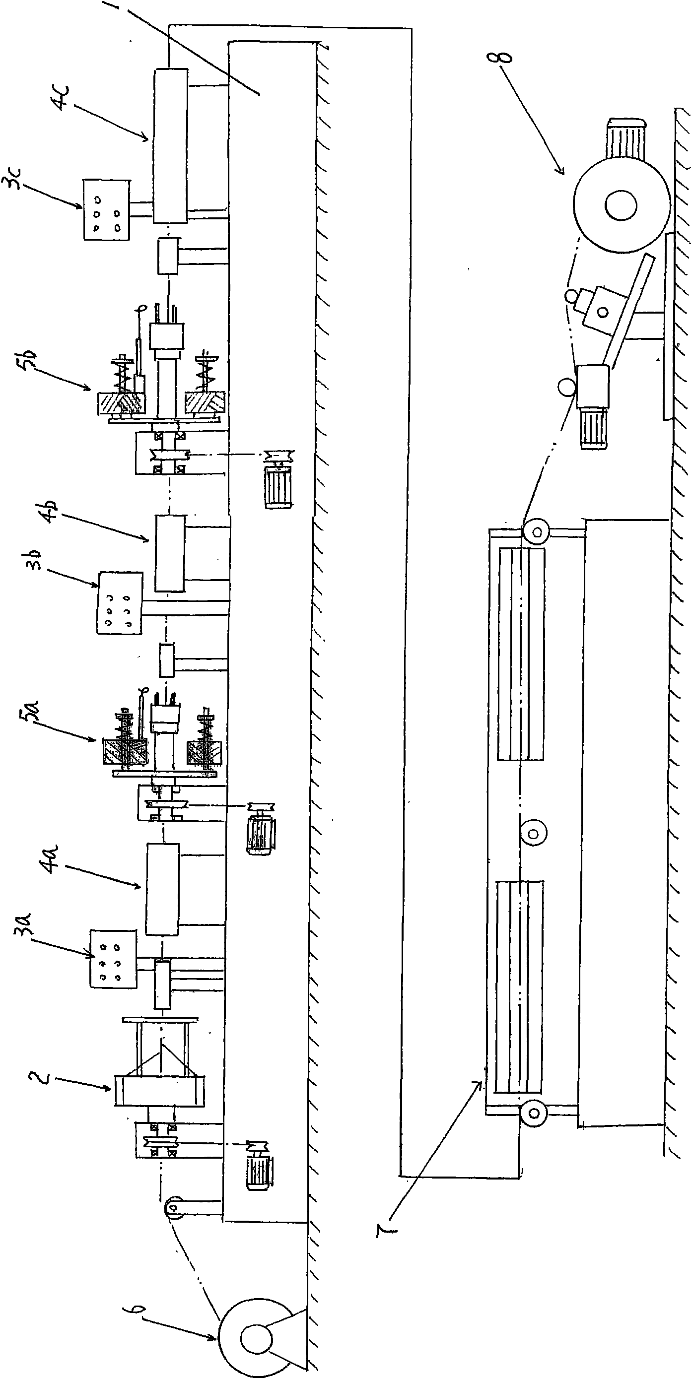
[0019] please see figure 1 , given the first and second machines 1 and 9, with the present figure 1 Take the position shown as an example, the left ends of the first and second machines 1 and 9 are called the front ends, the right ends are called the rear ends, the left end of the drying device 7 is the front end, that is, the entrance end, an...


PUM


Abstract

The invention relates to a film yarn covering and wrapping machine belonging to the technical field of process equipment of electric wires and cables, which comprises a first machine table, a pay-offstand, a drier, a take-up stand, an insulating film wrapping machine, a first console, a second console, a third console, a first maceration tank, a second maceration tank, a third maceration tank, afirst insulating yarn-band wrapping machine, a second insulating yarn-band wrapping machine and a second machine table, wherein the drier is arranged between the first machine table and the second machine table, and the take-up stand corresponds to the tail end of the second machine table; the insulating film wrapping machine, the first console, the first maceration tank, the first insulating yarn-band wrapping machine, the second console and the second maceration tank are sequentially arranged in the length direction of the surface of the first machine table; and the second insulating yarn-band wrapping machine, the third console and the third maceration tank are sequentially arranged in the length direction of the surface of the second machine table. The film yarn covering and wrapping machine can increase the bonding effect between insulating film layer and the conductor, the bonding force between the insulating film layer and the insulating yarn-band layer and the bonding force between the insulating yarn-band layers, enhance the production efficiency and ensure the product quality.

Description

technical field [0001] The invention belongs to the technical field of wire and cable processing equipment, and in particular relates to a thin film wire wrapping machine, which is used to coat the outer surface of flat or round bare wires, such as bare copper wires, aluminum wires or copper-clad aluminum wires, with an insulating film and insulating ribbon. Background technique [0002] The concept of the aforementioned film wire wrapping machine refers to wrapping the film and the insulation ribbon layer separately outside the bare conductor. The outside acts as a surface insulation. [0003] The above-mentioned wires coated with insulating films and insulating ribbons are widely used in coils of high-power generators, transformers and high-voltage motors. As is well known in the industry, the reason why the insulation ribbon is wrapped (wrapped) outside the film insulation layer is because the mechanical strength of the insulation film is limited, and the film layer is ...

Claims


Application Information

Patent Timeline
Patent Type & Authority Applications(China)
IPC IPC(8): H01B13/06H01B13/08H01B13/16H01B13/30
Inventor 秦宇孙建忠
Owner CHANGSHU HAOWEIFU MACHINERY MFG
Why Eureka
Try Eureka