Relay utilizing fault transient state current component protection and application method thereof

A transient current and relay technology, applied in emergency protection circuit devices, electrical components, circuit devices, etc., can solve problems such as relay malfunction, difficulty in determining the specific location of the fault line, and inability to determine the fault location, etc. Quick, high fault detection accuracy, simple composition effect

Inactive Publication Date: 2010-02-03
XI AN JIAOTONG UNIV
View PDF0 Cites 20 Cited by
  • Summary
  • Abstract
  • Description
  • Claims
  • Application Information

AI Technical Summary

Problems solved by technology

[0009] For faults close to the busbar in the prior art, it is difficult to determine the specific location of the fault line by relying on the time tracking signal of GPS, which may lead to misoperation of the relay; although the polarity comparison protection has high reliability in determining the fault section However, the specific fault location cannot be determined. The present invention proposes a technical solution for relays protected by fault transient current components:

Method used


Image

  • Relay utilizing fault transient state current component protection and application method thereof
  • Relay utilizing fault transient state current component protection and application method thereof
  • Relay utilizing fault transient state current component protection and application method thereof

Examples


Embodiment Construction

[0029] The present invention will be further described in detail below in conjunction with the accompanying drawings and embodiments.

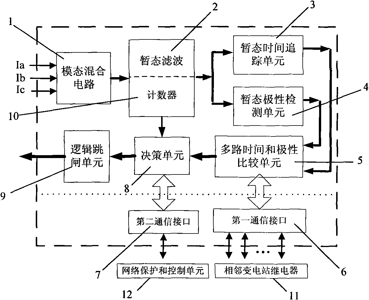
[0030] The relay utilizing fault transient current component protection of the present invention, such as figure 1 As shown, a relay using fault transient current component protection includes a modal hybrid circuit 1, a transient filter unit 2, a counter 12, a transient time tracking unit 3, a transient polarity detection unit 4, a multi-channel time and Polarity comparison unit 5, decision-making unit 8, logic tripping unit 9, first communication interface 6 and second communication interface 7; modal hybrid circuit 1 converts the three-phase current it receives into a modulus signal and inputs it to the connected A transient filtering unit 2; a transient time tracking unit 3 and a transient polarity detection unit 4 are arranged in parallel between the transient filtering unit 2 and the multi-channel time and polarity comparison unit 5, and...


PUM


Abstract

The invention discloses a relay utilizing fault transient state current component protection, comprising a modal hybrid circuit, a transient state filtering unit, a counter, a transient state time tracing unit, a transient state polarity detection unit, a multipath time and polarity comparison unit, a decision unit, a logic trapping unit, a first communication interface (6) and a second communication interface (7). An application method comprises the following steps: 1) supposing a fault occurred in Point F1; 2) generating high frequency signals by a fault phase and a non-fault phase; 3) sending data to an adjacent relay by a relay; 4) comparing the polarity and transient state time of a first wave with information recorded in other relays by each relay; 5) determining the tripping breaker, if a time difference of the transient state current reaching the two ends of an electricity transmission circuit is less than the ratio of the length of the electricity transmission circuit to the wave speed of the transient state current, and the polarities of the transient state current signals detected at the two ends of the electricity transmission circuit are the same; 6) determining the fault position by a time difference of a traveling wave reaching the two ends of the fault circuit; and 7) preventing the breaker from trapping by the relay, if the time difference of the transient state current reaching the two ends of the electricity transmission circuit is equal to the ratio of the length of the electricity transmission circuit to the wave speed of the transient state current andthe polarities of the transient state current signals detected at the two ends of the electricity transmission circuit are different. The invention has the advantages of high detection precision, quick response and low cost.

Description

Technical field: [0001] The invention belongs to the field of relay protection of power systems, and relates to a relay for protection using fault transient current components and an application method thereof. Background technique [0002] A century has passed since the overcurrent relay first appeared in the power system. Protection device technology has developed from electromechanical, transistor, and integrated circuit to microprocessor. At present, in the field of power system protection, digital relays based on microprocessors have gradually replaced traditional relays. However, various protection principles based on power frequency signals still play a leading role. [0003] In the late 1970s, with the continuous expansion of the power network, the need to quickly clear faults and improve system stability has aroused people's research enthusiasm for using non-power frequency fault detection technology to improve the response speed of relays. This has led to the st...

Claims


Application Information

Patent Timeline
Patent Type & Authority Applications(China)
IPC IPC(8): H02H7/26H02J13/00
CPCY04S10/20Y02E60/725Y02E60/00
Inventor 张保会郝治国薄志谦安德鲁·克莱门克周良才
Owner XI AN JIAOTONG UNIV
Why Eureka
Try Eureka