
Liquid supplying and draining device of evaporating and cooling system of water wheel generator stator

A technology for generator stators and hydroelectric generators, applied in cooling/ventilation devices, electromechanical devices, electrical components, etc., can solve the problems of hidden dangers in use, large dielectric loss, time-consuming and labor-intensive problems, and reduce intermediate losses and facilitate Control and ensure the effect of safety

Active Publication Date: 2010-02-03
INST OF ELECTRICAL ENG CHINESE ACAD OF SCI
View PDF1 Cites 13 Cited by
  • Summary
  • Abstract
  • Description
  • Claims
  • Application Information

AI Technical Summary

Problems solved by technology

[0004] For small and medium-sized evaporative cooling hydro-generators, such as 50 megawatts, the medium required for each motor is about 300 kg, which can be completed by manual liquid supply and drainage. For large-scale evaporative cooling hydro-generators, such as 700 MW , the medium required for each motor is about 3 tons, and it is very difficult to manually supply and discharge liquid, especially for large hydroelectric generators in underground power stations, which is time-consuming and labor-intensive
Moreover, since the artificial liquid supply and discharge in the prior art is a non-sealed system, large dielectric losses may occur during the liquid supply and discharge operation, and there are certain safety hazards in its use.

Method used


Image

  • Liquid supplying and draining device of evaporating and cooling system of water wheel generator stator

Examples


Embodiment Construction

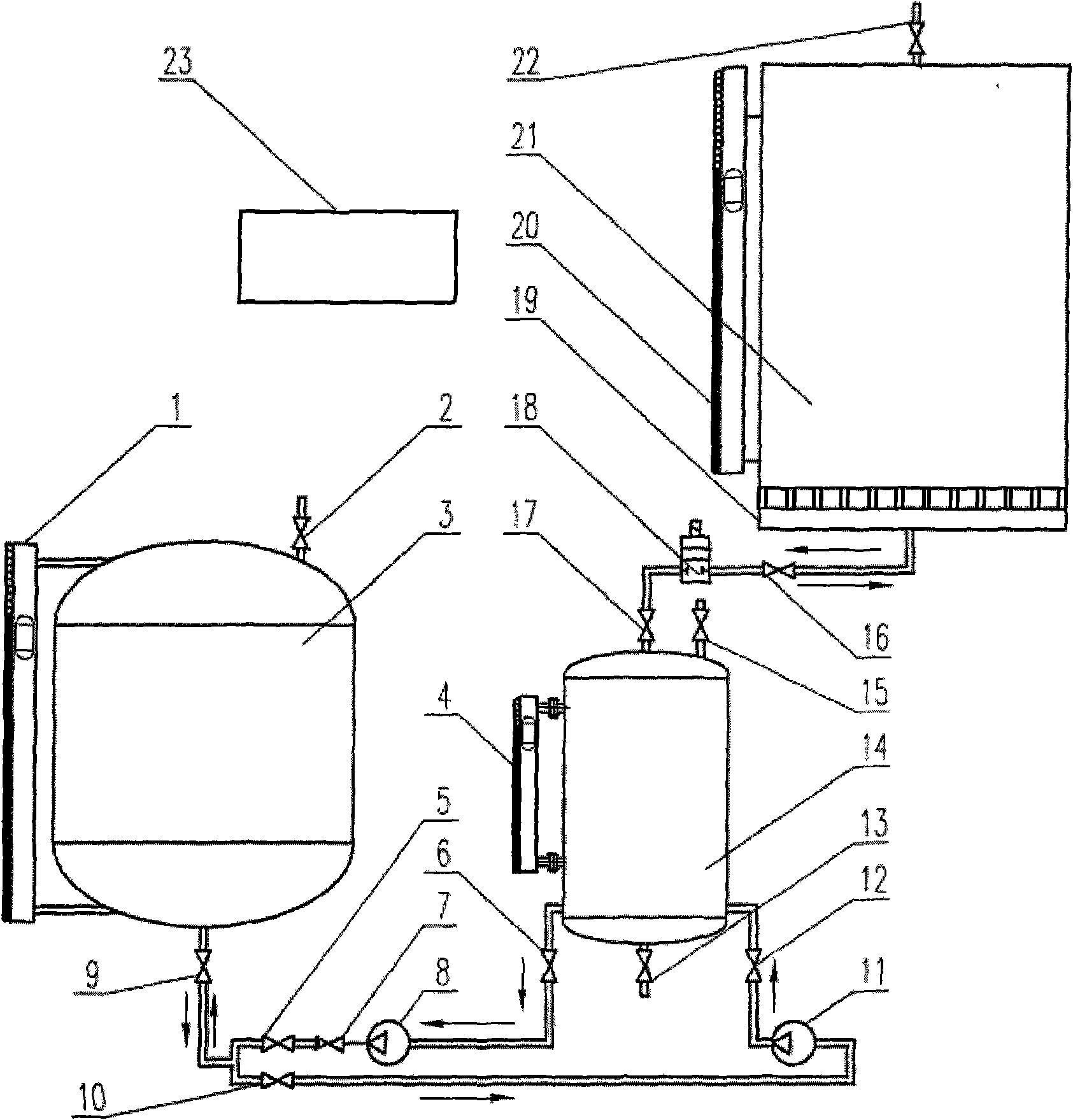
[0025] The liquid supply and discharge device of the present invention comprises a liquid supply branch, a liquid discharge branch and a power / control cabinet (23) for providing a power supply and a control circuit.

[0026]figure 1 is an embodiment of the present invention. Such as figure 1 As shown, a stainless steel pipe fitting is welded at the lowest position of the liquid collecting pipe 19, and a flange is welded at the other end of the pipe fitting, and the device of the present invention is installed on the stator evaporative cooling system 21 of the hydro-generator through the flange ball valve 16. A liquid level gauge 20 and an air release valve 22 are installed on the stator evaporative cooling system 21 of the hydro-generator, and the position of the entire liquid supply and discharge device is lower than the liquid collection pipe 19 . The liquid supply / discharge solenoid valve 18 is connected to the liquid collecting pipe 19, and an inspection valve 16 is arran...


PUM


Abstract

The invention relates to a liquid supplying and draining device of an evaporating and cooling system of a water wheel generator stator, comprising a liquid supplying branch pipe and a liquid drainingbranch pipe. The liquid supplying branch pipe comprises a liquid storing tank (3), a liquid supplying valve (10), a liquid supplying pump (11), a transitional tank (14) and a liquid supplying / drainingelectromagnetic valve (18) which are connected with a liquid collecting pipe (19) of the evaporating and cooling system of the generator stator in sequence according to the flowing direction of the medium; the liquid supplying pump (11) is positioned at the lowest position of the liquid supplying and draining device. In the liquid draining branch pipe, the liquid collecting pipe (19), the liquidsupplying / draining electromagnetic valve (18), the transitional tank, a liquid draining pump (8), a check valve (7), a liquid draining valve (5) and the liquid storing tank (3) of the evaporating andcooling system of the generator stator are connected in sequence according to the flowing direction of the medium; and the liquid draining pump (8) is positioned at the lowest position of the whole device. The power supply and the control of the whole device is provided by a liquid supplying and draining hydraulic / control cabinet (23).

Description

technical field [0001] The invention relates to an evaporative cooling system for a hydroelectric generator stator, in particular to a liquid supply and discharge device for the evaporative cooling system. Background technique [0002] Large hydroelectric generators are usually air-cooled and water-cooled. The air cooling unit is an external cooling technology, which is cooled by external air blowing of the winding, and the cooling effect is poor. At the same time, due to the limitation of the ultimate capacity, this cooling method limits the development of the hydroelectric generator to a larger capacity. Water cooling is to pressurize the water pump to make water flow inside the hollow wire of the winding to take away the heat. Because the specific heat of water is large and the viscosity is small, the cooling effect is better, but the pressure that needs to drive the water circulation is relatively high. In the case of water and electricity separation The joints are pro...

Claims


Application Information

Patent Timeline
IPC IPC(8): H02K9/20
Inventor 余顺周袁佳毅宋福川阮琳田新东刘斐辉
Owner INST OF ELECTRICAL ENG CHINESE ACAD OF SCI
Learn More