Flywheel motor adopting no-cross one-range winding

A flywheel motor and single-plane technology, applied in the field of motors, can solve problems such as poor torque stability, large power consumption, and complex structure, and achieve the effects of stable operation, low loss, and small size

Inactive Publication Date: 2010-02-03
HARBIN INST OF TECH
View PDF0 Cites 17 Cited by
  • Summary
  • Abstract
  • Description
  • Claims
  • Application Information

AI Technical Summary

Problems solved by technology

[0005] In order to solve the problems of complex structure, large power consumption and poor torque stability of

Method used


Image

  • Flywheel motor adopting no-cross one-range winding
  • Flywheel motor adopting no-cross one-range winding
  • Flywheel motor adopting no-cross one-range winding

Examples


specific Embodiment approach 1

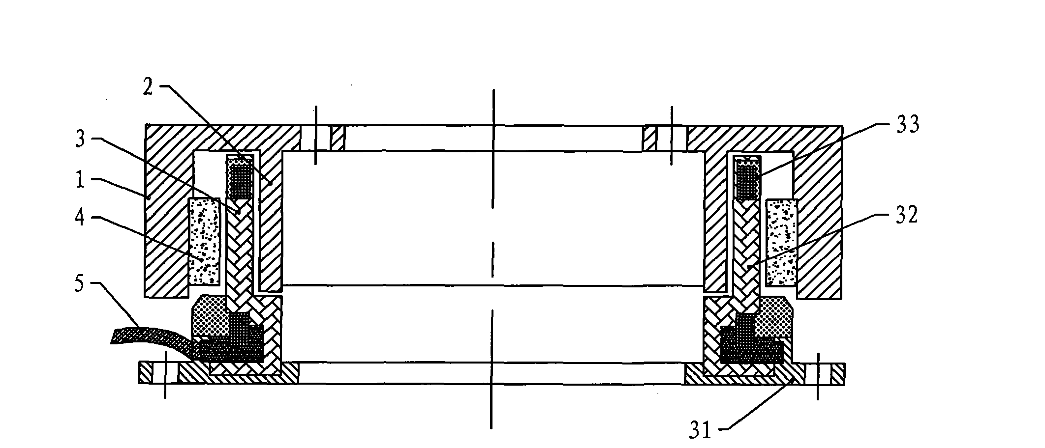
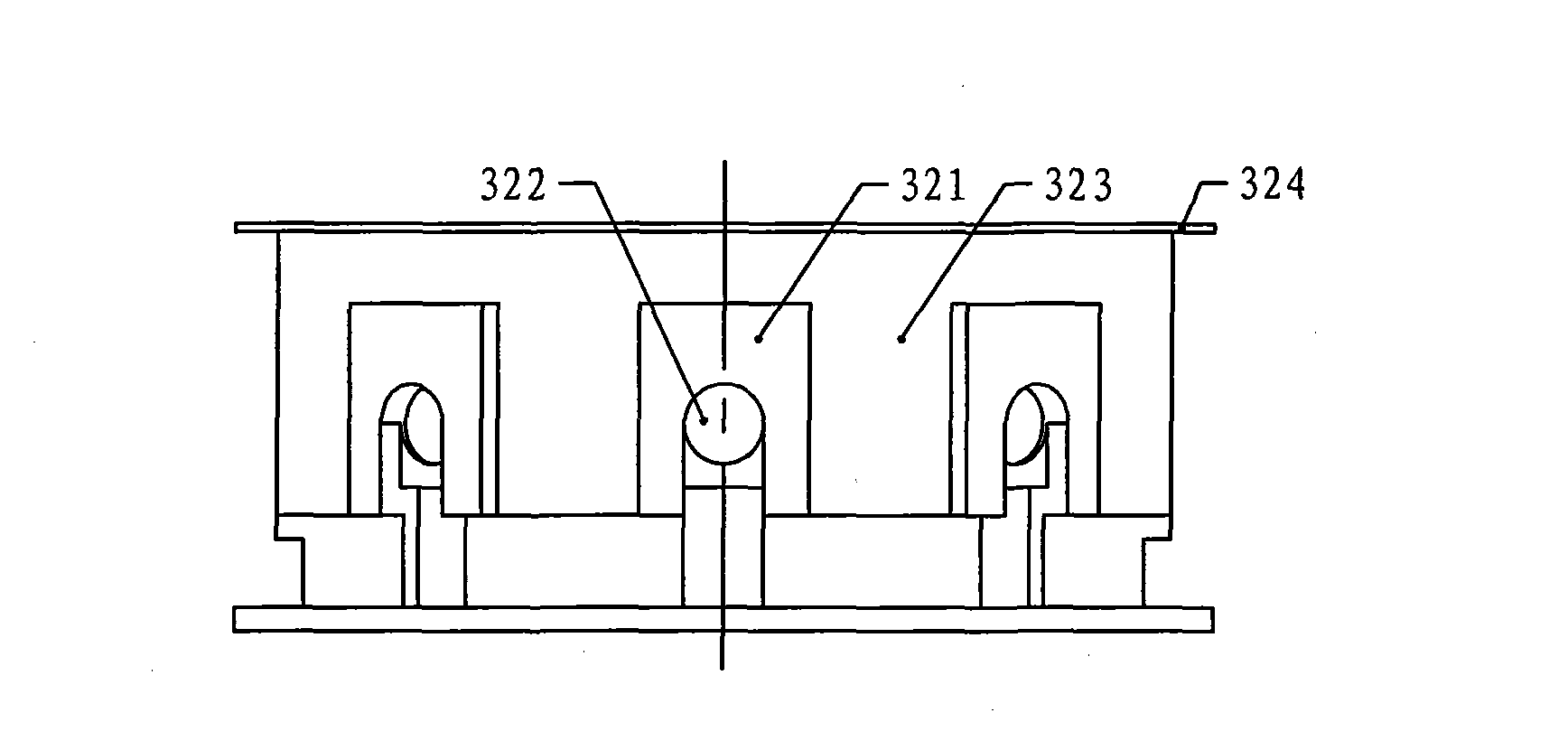
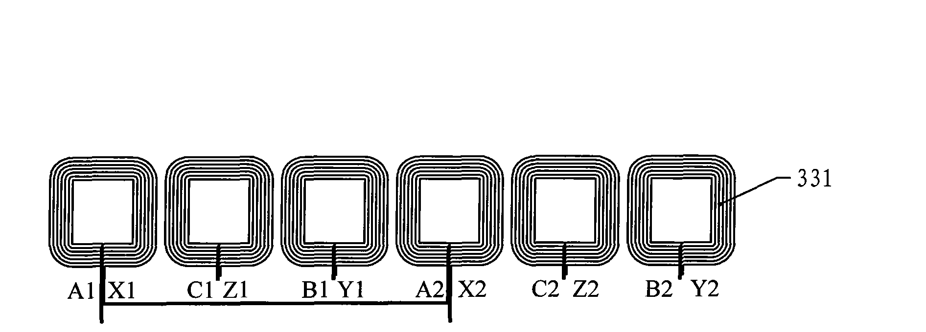
[0017] Specific implementation mode one: see figure 1 This embodiment will be described. The flywheel motor using non-crossing single-plane windings described in this embodiment is composed of a rotor, a coreless skeleton stator 3, a permanent magnet 4 and three position sensors. The rotor is composed of an outer rotor core 1 and an inner rotor core 2. The inner rotor core 2 and the outer rotor core 1 are fixedly connected on the torque output shaft, and the coreless skeleton stator 3 is fixed between the inner rotor core 2 and the outer rotor core 1, and is connected with the inner rotor core 2 and the outer rotor core. There is an air gap between the rotor cores 1, and the permanent magnet 4 is fixed on the inner rotor core 2 or the outer rotor core 1 on the side wall opposite to the coreless frame stator 3, and the coreless frame stator 3 is composed of a winding 33 , a skeleton 32 and a stator base 31, the skeleton 32 is fixed on the stator base 31, the winding 33 is a th...

specific Embodiment approach 2

[0037] Specific Embodiment 2: The difference between this embodiment and the flywheel motor without intersecting single-plane winding described in Specific Embodiment 1 is that the inner rotor core 2 and the outer rotor core 1 are split structures, and the inner rotor core 2 and one end of the outer rotor core 1 are connected by a beam 21 and fixed with screws.

[0038] In this embodiment, the inner rotor core 2 and the outer rotor core 1 adopt a split structure, which makes the installation of the permanent magnet 4 more flexible and facilitates production.

specific Embodiment approach 3

[0039] Embodiment 3: The difference between this embodiment and the flywheel motor without intersecting single-plane winding described in Embodiment 1 or 2 is that the permanent magnet 4 is fixed on the outer wall of the inner rotor core 2 .


PUM

PropertyMeasurementUnit
Thicknessaaaaaaaaaa

Abstract

The invention discloses a flywheel motor adopting a no-cross one-range winding, relating to the technical field of the motor and solving the problems that the existing flywheel motor has complex structure, large power consumption and poor moment stability. A rotor in the invention is a wheel body of a flywheel; an outer rotor iron core and an inner rotor iron core of the rotor are fixedly connected on a torque output shaft; a no-iron core frame type stator is fixed between the inner rotor iron core and the outer rotor iron core; permanent magnets are fixed on the inner rotor iron core or the outer rotor iron core and the side wall corresponding to the no-iron core frame type stator; a winding of the no-iron core frame type stator consists of a plurality of groups of planar coils which areevenly distributed and fixed on the side wall of the frame; two adjacent groups of planar coils have an electric angle of 240 degrees, and have no cross; three position sensors are respectively fixedon the frames at the central positions of three adjacent groups of planar coils; and the ratio of the number Z of the planar coils and the number 2p of poles of the permanent magnets is 3/4. The flywheel motor is applicable to the technical fields of posture control of the satellites and control moment gyros and the like.

Description

technical field [0001] The invention relates to the technical field of motors. In particular, it relates to a brushless direct current motor adopting non-interleaved single-plane winding. Suitable for satellite attitude control. Background technique [0002] At present, most flywheels for satellite attitude control are composed of an independent wheel body and a brushless DC motor, and the two are fixed by mechanical structures such as flanges. There are problems such as complex structure and difficulty in miniaturization and weight reduction of the flywheel. [0003] The winding structure of the brushless DC motor with traditional structure is slightly complicated, which is not conducive to the realization of ironless armature. [0004] The position sensor of the traditional motor usually requires additional installation mechanism and space, and generally detects the leakage magnetic field, the position detection accuracy and reliability are poor, and the position of the...

Claims


Application Information

Patent Timeline
IPC IPC(8): H02K29/06H02K29/03H02K3/28H02K1/27
Inventor 胡建辉邹继斌徐永向刘承军尚静李勇
Owner HARBIN INST OF TECH
Why Eureka
Try Eureka