
Method and device for producing a tomosynthetic 3d x-ray image

A tomosynthesis and X-ray technology, which is applied to instruments for radiological diagnosis, X-ray tube cold cathodes, X-ray tube cathode assemblies, etc. The effect of increasing the possibility of adjustment

Inactive Publication Date: 2010-02-03
SIEMENS AG
View PDF3 Cites 18 Cited by
  • Summary
  • Abstract
  • Description
  • Claims
  • Application Information

AI Technical Summary

Problems solved by technology

This results in a low signal-to-noise ratio for both the obtained 2D projection images and the computed 3D X-ray images

Method used


Image

  • Method and device for producing a tomosynthetic 3d x-ray image

Examples


Embodiment Construction

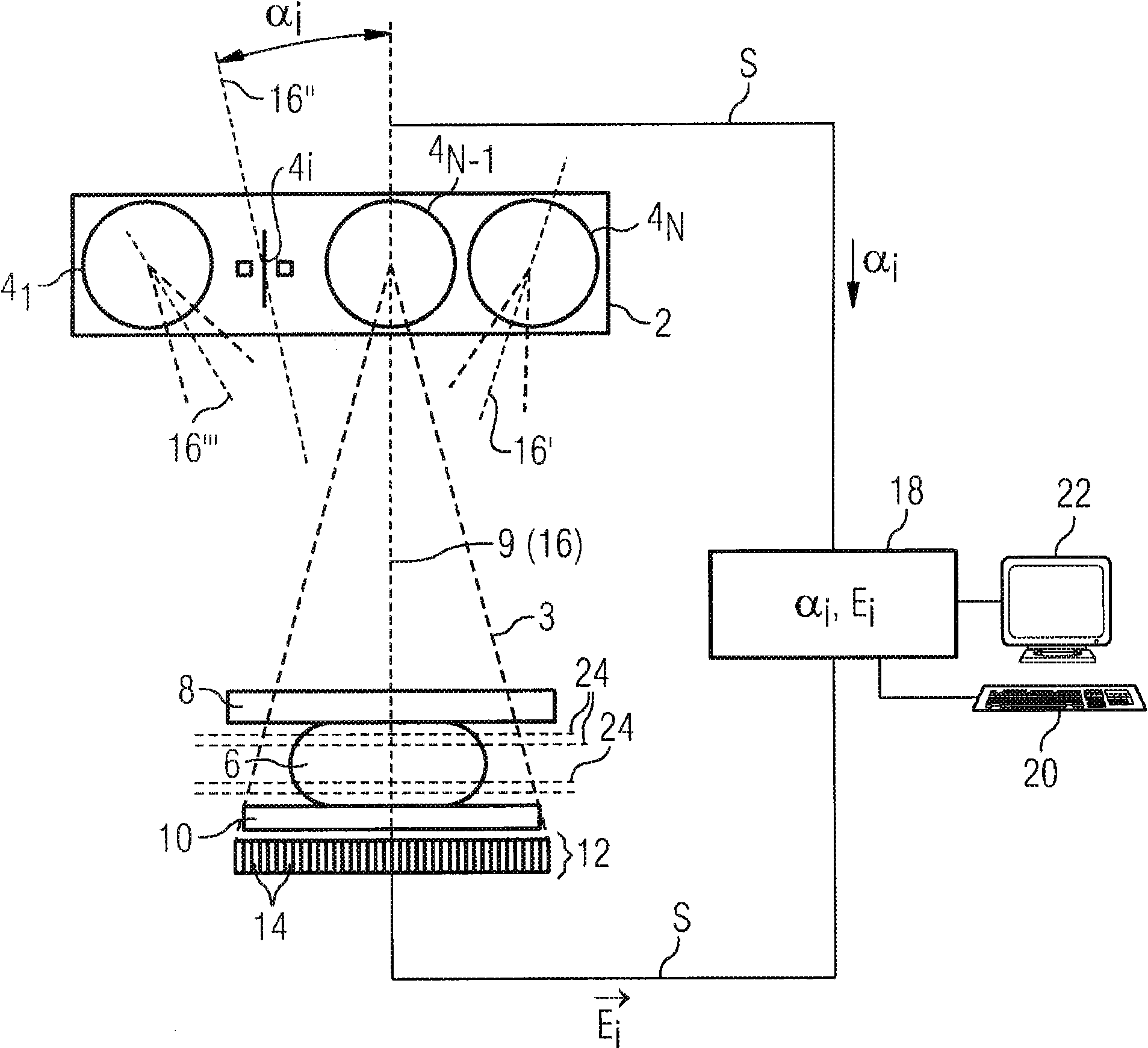
[0023] The drawing shows a mammography system with an x-ray source 2 having a plurality of emitters 4 . The X-ray source 2 in the accompanying drawings has N emitters 4 1 to 4 N . The individual emitters 4 are arranged side by side in an array and generate X-rays 3 for irradiating an object 6 to be examined (in this example a female breast). The arrangement adopted by each emitter 4 can make it irradiate the object 6 to be inspected under different angles α. Among them, the i-th emitter 4 i The angle between the irradiation direction 16″ and a surface normal 9 is the angle α i . In order to be able to adjust the radiation directions 16 , 16 ′, 16 ″, 16 ″′, the emitters 4 can be arranged in the x-ray source 2 so as to be slightly offset relative to one another.

[0024] The object 6 to be inspected is fixed between a pressing plate 8 and a bearing plate 10 . An X-ray detector 12 is arranged on the side of the object 6 away from the X-ray source 2, and the X-ray detector ...


PUM


Abstract

In a method and device for producing a tomosynthetic 3D x-ray image, a number of 2D projection images of an examination subject are acquired using a fixed x-ray source. The x-ray source has multiple,individually controllable emitters that respectively emit a single x-ray dose from various different directions. The tomosynthetic 3D image is reconstructed from the individual 2D projection images, and at least one 2D projection image is composed of multiple individual images.

Description

technical field [0001] The invention relates to a method particularly suitable for mammography and a device for producing a tomosynthetic three-dimensional x-ray image. In this tomosynthesis method, a plurality of X-ray images of an object to be examined are taken from different directions. The tomosynthetic three-dimensional X-ray image is subsequently calculated from the two-dimensional projection images obtained in this way. Background technique [0002] A tomosynthesis three-dimensional X-ray image is an image data set composed of a plurality of tomographic images. Such image data sets obtained by reconstruction of two-dimensional projection images are referred to hereinafter as "tomosynthesis three-dimensional X-ray images" or "three-dimensional tomosynthesis images". [0003] Mammography is an X-ray examination of the breast with the aim of detecting malignant tumors as early as possible. Through continuous improvement of imaging methods, efforts are being made to g...

Claims


Application Information

Patent Timeline
Patent Type & Authority Applications(China)
IPC IPC(8): G01N23/04A61B6/00
CPCA61B6/542A61B6/466A61B6/482A61B6/405A61B6/502A61B6/4085H01J2235/062H01J2235/068A61B6/4028A61B6/032
Inventor 托马斯·默特尔迈尔
Owner SIEMENS AG
Learn More