Communication apparatus for rolling stock

A technology for railway vehicles and communication devices, which is applied to data exchange through path configuration, digital transmission systems, electrical components, etc., and can solve problems such as reduced transmission speed, increased frequency of transmission data retransmission, and consideration of transmission line signal quality. , to achieve the effect of ensuring adaptability and improving reliability

Inactive Publication Date: 2010-02-03
MITSUBISHI ELECTRIC CORP
View PDF1 Cites 16 Cited by
  • Summary
  • Abstract
  • Description
  • Claims
  • Application Information

AI Technical Summary

Problems solved by technology

[0005] However, in the railway vehicle communication device disclosed in the above-mentioned Patent Document 1, although the transmission line built in the vehicle or between vehicles or the failure of the equipment is considered, the signal quality of the transmission line is not con

Method used


Image

  • Communication apparatus for rolling stock
  • Communication apparatus for rolling stock
  • Communication apparatus for rolling stock

Examples


Embodiment Construction

[0053] Hereinafter, preferred embodiments of the railway vehicle communication device according to the present invention will be described in detail with reference to the drawings. In addition, this invention is not limited to the following embodiment.

[0054] (Overview of Railway Vehicle Communication System)

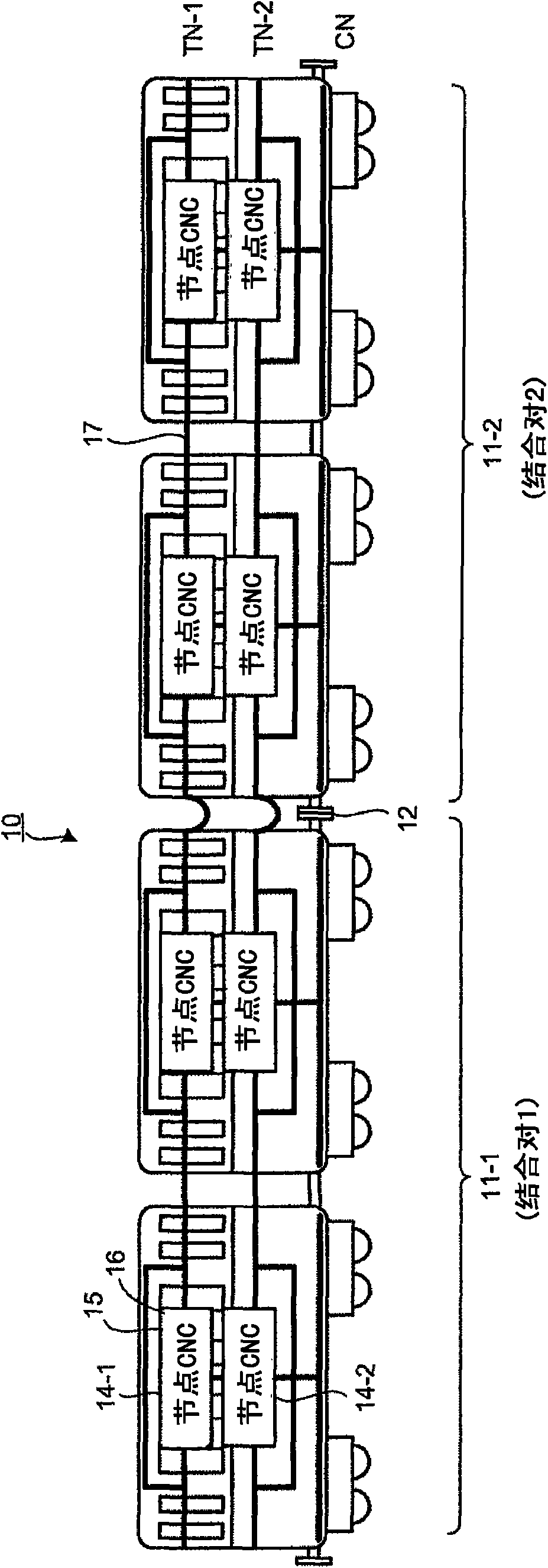
[0055] First, an outline of a railway vehicle communication system equipped with a railway vehicle communication device will be described. figure 1 It is a schematic configuration diagram showing a railway vehicle communication system equipped with a railway vehicle communication device according to a preferred embodiment of the present invention. In the example shown in this figure, the vehicle group 11-1 (Married_pair_1: combined pair 1) and the vehicle group 11-2 (Married_pair_2: combined pair 2) connected in units of two vehicles are connected by the automatic coupler (Automatic Coupler) 12 are connected to form a railway vehicle 10, and each vehicle of the rail...


PUM


Abstract

A railway-train communication apparatus provided in a railway train secures the adaptability to a transmission path having low signal quality and improves the certainty of data transmission. The railway-train communication apparatus includes a node device 21, which includes converters 31-1 and 31-2 that perform a mutual signal conversion between an HDLC signal flowing through an inter-car networkconstructed between cars of the railway train and an Ethernet (registered trademark) signal flowing through an in-car network constructed in each of the cars and switching hubs 32 arranged between theconverters 31-1 and 31-2 and for respectively connecting the converters 31-1 and 31-2, and network controllers 22-1 and 22-2 that are connected to the switching hubs 32.

Description

technical field [0001] The present invention relates to a railway vehicle communication device provided in a railway vehicle and providing a communication function of a railway vehicle communication system. Background technique [0002] Conventionally, there is a communication device for railway vehicles, the components of which include a structural control unit having a carrier sense multiple access interface, a switching hub for bifurcating the transmission line, and a switching hub that cuts off the input and output signals of the switching hub. The switch is used to control the communication state of the uplink and downlink directions of the transmission line by connecting and disconnecting the switch, so as to identify the structure and connection form of the communication equipment in the train (for example, the following patent document 1). [0003] In the railway vehicle communication device disclosed in this patent document 1, a switching hub is used to connect the ...

Claims


Application Information

Patent Timeline
IPC IPC(8): H04L12/40H04L12/46H04L12/28
CPCH04L49/00H04L49/602H04L49/35H04L67/12H04L49/351H04L12/4625H04L2012/40293H04L29/08558
Inventor 竹山雅之辰巳尚吾吉田实
Owner MITSUBISHI ELECTRIC CORP
Why Eureka
Try Eureka