Eureka AIR delivers breakthrough ideas for toughest innovation challenges, trusted by R&D personnel around the world.

Structure of fuel supply part

A technology of supply part and fuel, which is applied to the layout, vehicle components, power plant, etc. combined with the fuel supply of internal combustion engines, which can solve the problems of water intrusion and difficulty in stabilizing the tip accuracy.

Inactive Publication Date: 2010-02-10
HONDA MOTOR CO LTD
View PDF1 Cites 3 Cited by
  • Summary
  • Abstract
  • Description
  • Claims
  • Application Information

AI Technical Summary

Problems solved by technology

[0004] However, in the fuel cap of Patent Document 1, since the pressing member (push-up member) penetrates the recess integrally provided on the plate of the main body, water may intrude from the through hole of the recess.
Therefore, for example, it is conceivable to embed a sealing member made of rubber on the pushing member (push-up member) for sealing, or to shape the periphery of the through hole with the sealing member to seal, but due to the elasticity of the sealing member, the pushing The top of the pressing part (push-up part) swings, that is, there is a problem that the accuracy of the top is difficult to stabilize

Method used


Image

  • Structure of fuel supply part
  • Structure of fuel supply part
  • Structure of fuel supply part

Examples


Embodiment Construction

[0047] The best mode for use in the present invention will be described with reference to the drawings.

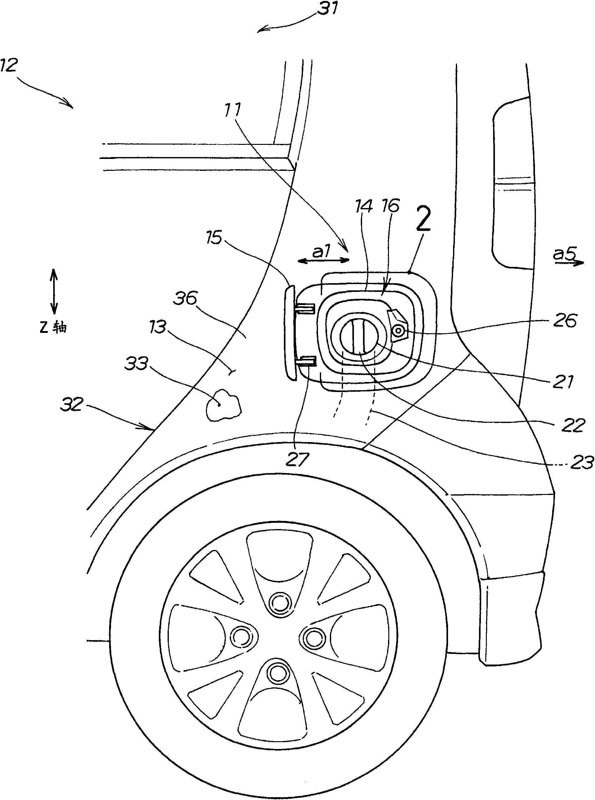
[0048] figure 1 It is a front view of the structure of the fuel supply part of this invention.

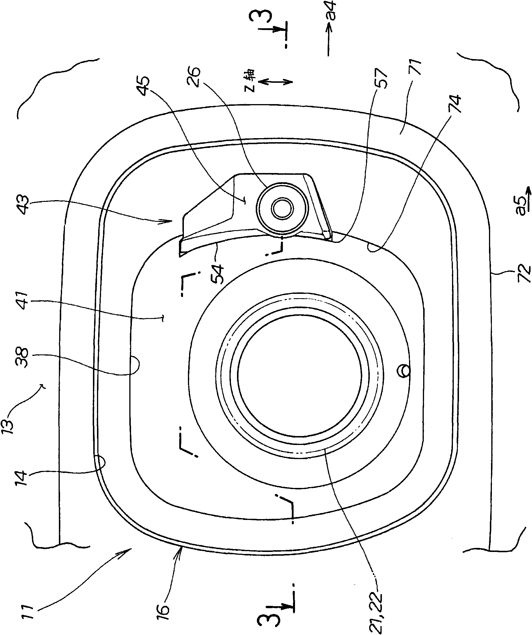
[0049] The fuel supply part structure 11 is used on the vehicle 12 and has: a fuel cap 15 provided on the opening 14 of the outer panel 13 of the vehicle 12 in a freely openable and closable manner (in the direction of the arrow a1); A substantially box-shaped fuel adapter 16 and a fuel supply port 21. 22 is a cap of the fuel supply port 21, and 23 is a fuel supply pipe for introducing fuel from the fuel supply port 21 to a fuel tank (not shown).

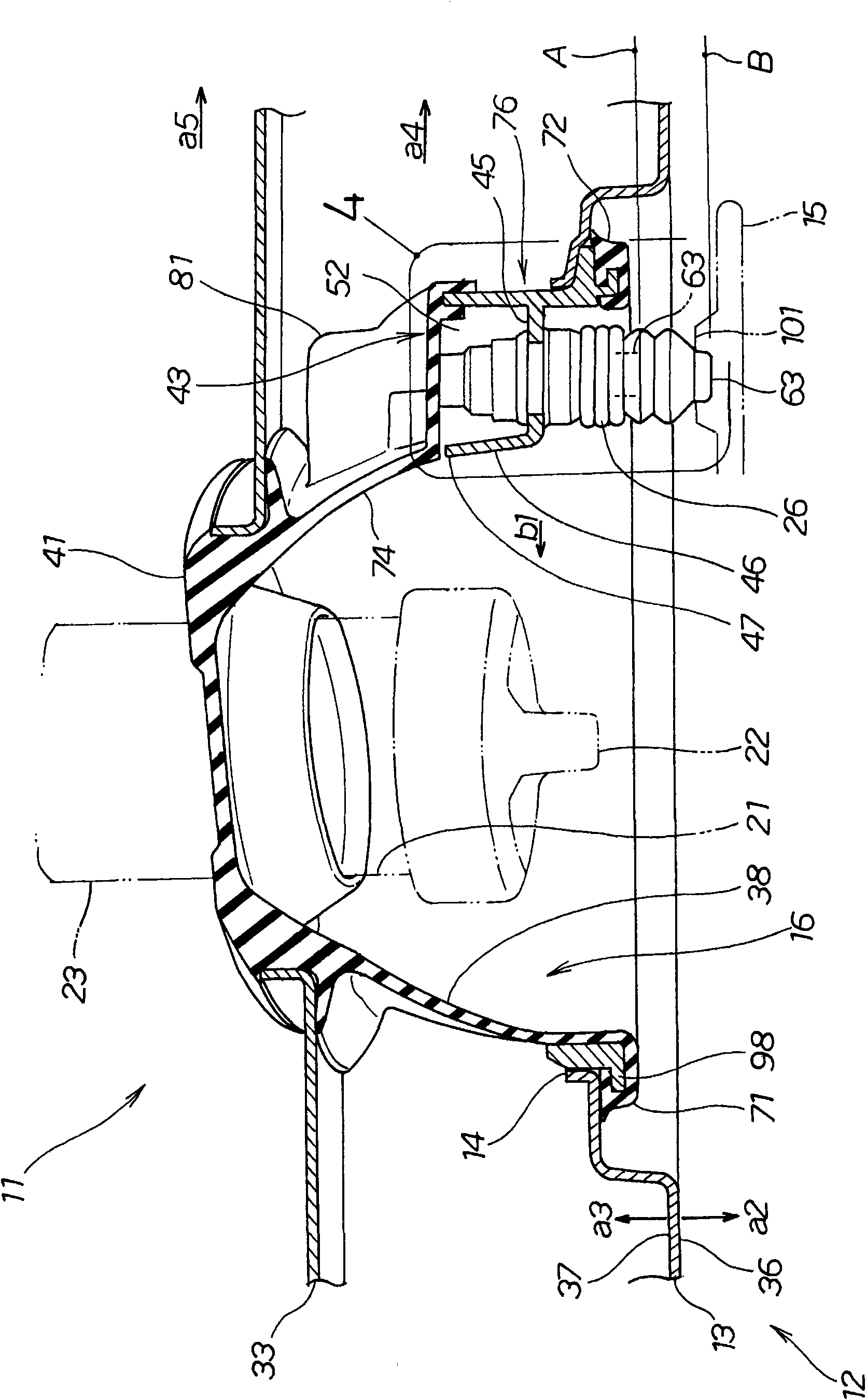
[0050] The operation when supplying fuel is the same as usual. First, the lock is released, and then, the closed fuel cap 15 is pushed from the outside, and the fuel cap 15 is opened by the pushing member 26 (refer to image 3 ). Fully open the fuel cap 15 by hand until the end ( figure 1 state) for oil supply.

[0051] The fu...


PUM


Abstract

The present invention provides a structure of a fuel supply part. The assembling precision of a pushing component can be sustained without setting a sealing component between the supporting components inserted with a pushing component (pushing lifting component). The structure (11) of the fuel supply part comprises the following components: a fuel adapter (16) which is provided with a side wall part (38) that extends from an opening (14) of an outer plate (13) of the vehicle (12) to the inner side of the vehicle (12), and a base (41) connected with the side wall part (38); a fuel cover (15) which seals the fuel adapter (16) and the opening (14) with a mode that the opening and closing can be performed freely; a pushing component (26) which pushes the fuel cover (15) through extending from a closing position (A) to an opening position (B), wherein a receiving dent (43) for receiving the pushing component (26) is formed through protruding the side wall part (38) to the outside of the fuel adapter (16). Furthermore the structure of the fuel supply part is provided with a supporting part (45) which is penetrated by the pushing component (26) in the receiving dent (43) and supports the pushing component.

Description

technical field [0001] The present invention relates to a vehicle fuel supply unit structure. Background technique [0002] In the structure of the fuel supply part, as is generally known, there is provided a pressing member (a push-up member) that opens a fuel cap that is opened during fuel supply from the inside (for example, refer to Patent Document 1). [0003] Patent Document 1: Japanese Unexamined Patent Publication No. 2005-67384 (page 9, image 3 ) [0004] However, in the fuel cap of Patent Document 1, since the pressing member (push-up member) penetrates the recess integrally provided on the main body plate, water may intrude from the hole through which the recess passes. Therefore, for example, it is conceivable to embed a sealing member made of rubber on the pushing member (push-up member) for sealing, or to shape the periphery of the through hole with the sealing member to seal, but due to the elasticity of the sealing member, the pushing The tip of the pressi...

Claims


Application Information

Patent Timeline
IPC IPC(8): B60K15/04B60K15/05
Inventor 介川明洋
Owner HONDA MOTOR CO LTD
Why Eureka
Eureka Blog
Learn More