Assembling method of gypsum evacuated mould

An assembly method and cavity mold technology, which are applied in the fields of formwork/template/work frame, on-site preparation of building components, building components, etc., can solve the problem that the strength of reinforced concrete materials cannot be fully exerted, process prefabrication, and transport and unload mold boxes. Difficulties, large plane size of mold box production, etc., to achieve the effect of saving concrete, saving consumption, and high product integrity rate

Inactive Publication Date: 2011-08-24
贵州金三利科技建材有限公司
View PDF1 Cites 1 Cited by
  • Summary
  • Abstract
  • Description
  • Claims
  • Application Information

AI Technical Summary

Problems solved by technology

To meet the rib beam spacing requirements, the plane size of the mold box is too large, and there are considerable difficulties in processing prefabrication, handling, loading and unloading the mold box
To meet the requirements of the plane size of a single mold box, the spacing between ribs an

Method used


Image

  • Assembling method of gypsum evacuated mould
  • Assembling method of gypsum evacuated mould
  • Assembling method of gypsum evacuated mould

Examples


Embodiment 1

[0035] 1. Connect the four mold boxes to form a large mold box with the bottom exposed: the following combination figure 2 , Figure 5 , Image 6 Explain the specific implementation process. When in use, assembling several plaster cavity mold boxes according to the size of the frame column net includes the following steps:

[0036] (1) Lay horizontal building formwork 1 at the bottom of the floor at the construction site;

[0037] (2) Lay out the line on the formwork to determine the positions of the concrete rib beam 3 and the secondary rib beam 4 of the assembled fixed form box;

[0038] (3) Binding the steel bars of concrete rib beam 3 and secondary rib beam 4;

[0039] (4) Embedded power and telecommunications pipelines at the bottom of the secondary rib 4;

[0040] (5) Lay a number of prefabricated gypsum cavity mold boxes 5 in each regular space enclosed by the rib beam 3 or the secondary rib beam 4. The method is to place the bottom plane 12 of one mold box against the buildin...

Embodiment 2

[0046] 1. Connect the four mold boxes to form a large mold box, the bottom of the mold box is invisible and surrounded by concrete: the following combination figure 2 , Figure 5 , Figure 7 Explain the specific implementation process. When in use, assembling several plaster cavity mold boxes according to the size of the frame column net includes the following steps:

[0047] (1) Lay horizontal building formwork 1 at the bottom of the floor at the construction site;

[0048] (2) Lay out the line on the formwork to determine the positions of the concrete rib beam 3 and the secondary rib beam 4 of the assembled fixed form box;

[0049] (3) Bind the steel bars of the bottom cast-in-place slab 2 on the building template 1. A concrete protective layer pad is set between the slab reinforcement and the template.

[0050] (4) Binding the steel bars of concrete rib beam 3 and secondary rib beam 4;

[0051] (5) Embedded power and telecommunications pipelines at the bottom of the secondary rib ...

Embodiment 3

[0058] Embodiment 3: This embodiment further explains the implementation process. The present invention includes two aspects: Generally speaking, it is suitable for a plaster cavity mold body in which four mold boxes are assembled as a whole. On the other hand, four mold boxes are connected and assembled into one large mold box. Here are the following:

[0059] 1. The shape of the plaster cavity mold box

[0060] The principle to determine the shape of the mold box is to be suitable for assembling the four mold boxes into one; meet the strength requirements; save material and low cost; and the process of connection and assembly is simple.

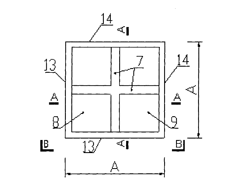
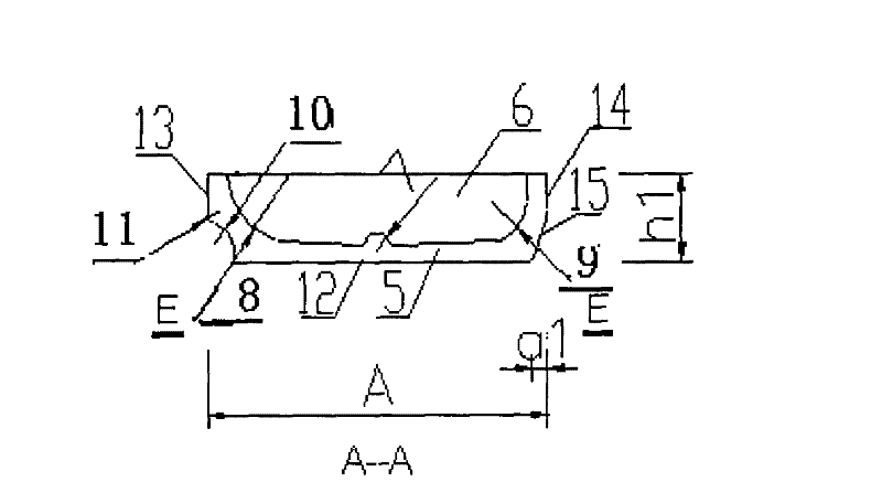
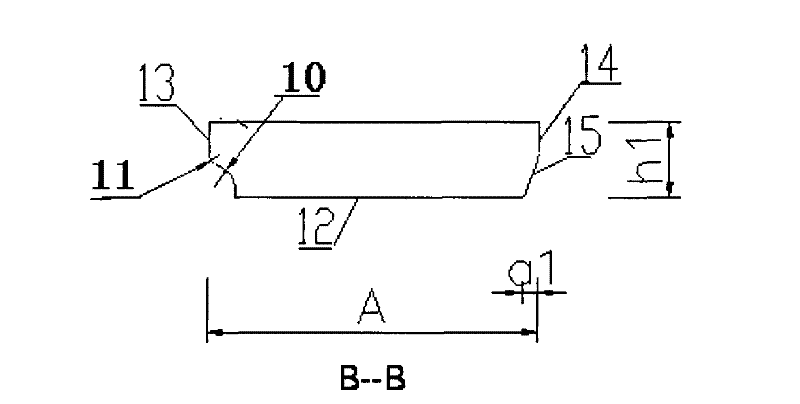
[0061] The plaster cavity mold box is shaped like Figure one As shown, the external dimension is A×A×h1. Including gypsum layer and cavity, the vertical surface is asymmetrical, the left side of the outer section is composed of vertical vertical surface, arc R1 and arc R2, and the right side of the outer section is made of lead It is composed ...


PUM


Abstract

The invention discloses an assembling method of gypsum evacuated mould, including paving a horizontal template at the bottom, determining positions of concrete beam and secondary girtstrip for assembling and fixing mould box, binding concrete beam and secondary girtstrip beam steel and embedding line pipes such as power and telecommunication and the like at the bottom of the secondary girtstrip. Floor plate beam steel is bound at the top of the gypsum evacuated mould box, concrete beam, secondary girtstrip and floor plate concrete are cast and vibrated, when concrete reaches designed age, thehorizontal template paved at the bottom is removed. Although connecting and assembling of mould box can be in multiple ways, the scheme shows that the assembling way of the invention is unique, the assembling method is combined with civil engineering construction, the mould box is embedded and fixed in steel concrete, no residual civil engineering construction procedure is produced, and the method is simple and feasible and is economic and practical. Contradiction of mould box production processing and architectural construction dimension requirement is solved, and the invention lays the foundation for the technology of making hollow floor system by promotion and application of concrete gypsum evacuated mould box in large scale.

Description

Technical field [0001] The invention relates to the field of building structures and building materials. Specifically, it is the method of assembling the plaster cavity mold. Background technique [0002] In the field of civil engineering, reinforced concrete is widely used due to its low cost and durability. For the floor system, it is usually composed of beams and slabs. The height of the beam is much larger than the thickness of the slab, and the beam should be exposed at the bottom of the slab to reduce the building clearance. When the span of the column network is large, in order to meet the rigidity requirements, the beam height needs to be increased to make the building clearance smaller. In order to overcome this defect and increase the rigidity of the floor, a multi-ribbed floor system appeared. Under the same span, the multi-ribbed beam has a smaller height, good rigidity and better stress. However, the shortcoming of multi-ribbed slabs is that the construction is ...

Claims


Application Information

Patent Timeline
IPC IPC(8): E04B5/18E04B5/36E04C1/00E04G15/06
Inventor 肖良锦马克俭刘建平刘海波杜礼昌
Owner 贵州金三利科技建材有限公司
Why Eureka
Try Eureka