Transmission passage responding detector
A technology of transmission path and predictor, which is applied in the direction of transmission system, electrical components, baseband system components, etc., can solve the problem of large circuit scale and achieve the effect of improving the prediction accuracy
- Summary
- Abstract
- Description
- Claims
- Application Information
AI Technical Summary
Problems solved by technology
Method used
Image

Examples
no. 1 approach
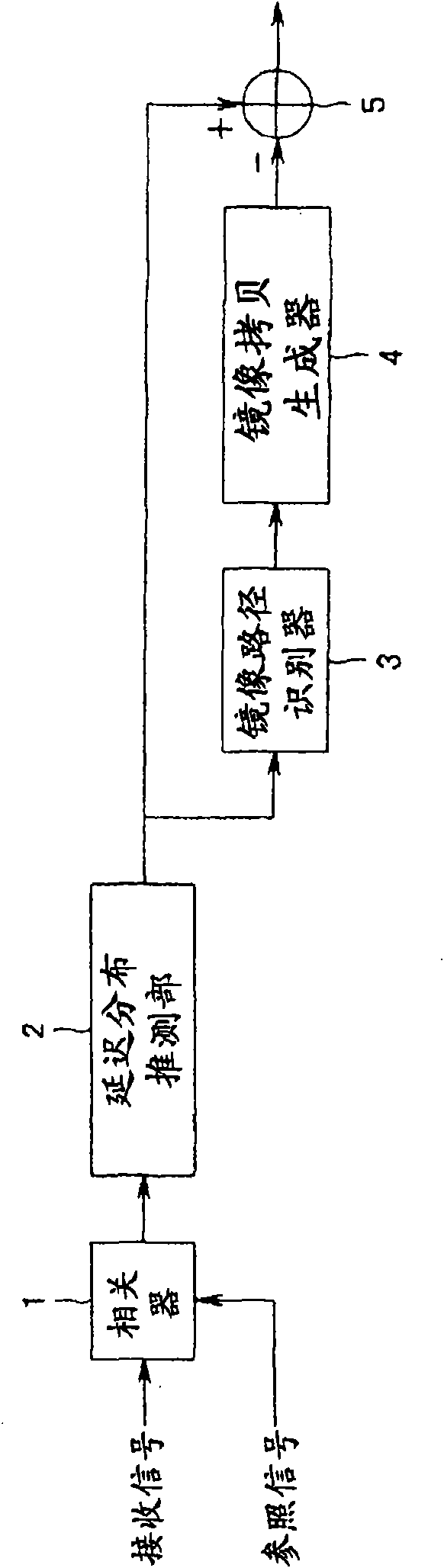
[0034] First, refer to figure 1 , the configuration of the channel response estimator according to the first embodiment of the present invention will be described. figure 1 It is a schematic block diagram illustrating the configuration of the channel response estimator according to the first embodiment of the present invention.
[0035] Such as figure 1 As shown, the transmission path response estimator of the first embodiment of the present invention includes: a correlator 1, which calculates the complex time correlation between a received signal and a reference signal; a delay profile estimator 2, which records the calculated delay time for each The delay distribution h(τ) is calculated by the correlation value; the mirror image path identifier 3 as the identification part recognizes the time position of the mirror image path as the false correlation peak according to the delay distribution h(τ); the mirror image copy as the pseudo copy generation part generates A device 4...
no. 2 approach
[0094] Next, refer to Figure 7 , the configuration of the channel response estimator according to the second embodiment of the present invention will be described. Figure 7 It is a schematic block diagram illustrating the configuration of the transmission path response estimator according to the second embodiment of the present invention.
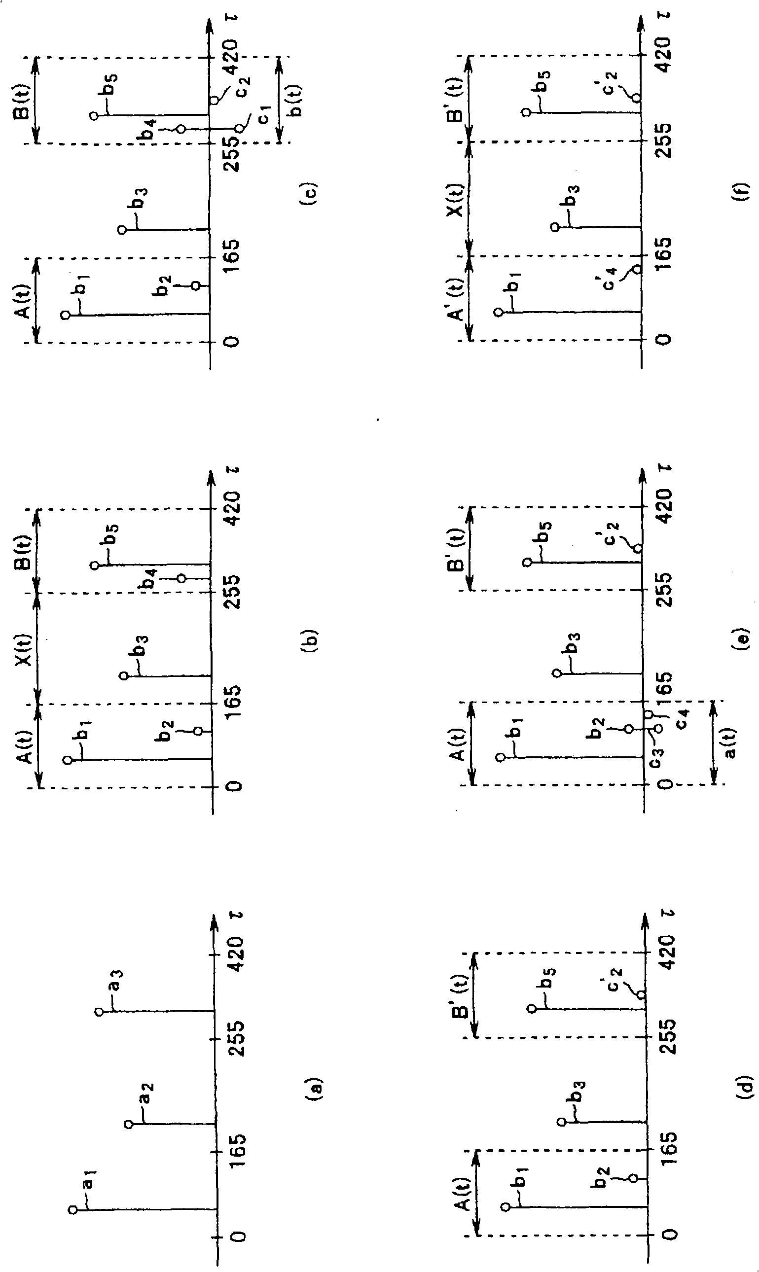
[0095] In the first embodiment, an image path is detected by making a delay profile from a received signal and a reference signal. On the other hand, the present embodiment differs in that two types of delay profiles are created using two different types of reference signals a and b for the received signal, and the difference between them is used to detect the image path.
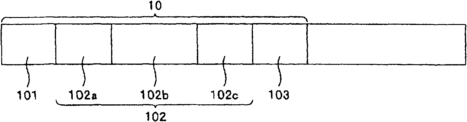
[0096] Similar to the first embodiment, the reference signal a is composed of the entire unique word including the code loop part (preamble code 101, PN sequence head area 102a, PN sequence end area 102c, and post code 103). Since the code length is long, the estimat...
no. 3 approach
[0115] Next, refer to Figure 11 , the configuration of the channel response estimator according to the third embodiment of the present invention will be described. Figure 11 It is a schematic block diagram showing the configuration of the channel response estimator according to the third embodiment of the present invention.
[0116] In the first embodiment, the mirror path is removed by generating a copy with respect to the path at the delay time at which the delayed path is detected, and subtracting the copy from the delay profile. On the other hand, in the present embodiment, by identifying the position (delay time) of the mirror path with respect to the path at the delay time of the detected delay path, and replacing the arrangement of the time with zero, the mirror path is removed. One point is different.
[0117] In an environment where the delay spread is small, there is no true delay path with high power at the position of the delay instant where the image path is g...
PUM
 Abstract
Description
Claims
Application Information
 - R&D
- Intellectual Property
- Life Sciences
- Materials
- Tech Scout
- Unparalleled Data Quality
- Higher Quality Content
- 60% Fewer Hallucinations
Browse by: Latest US Patents, China's latest patents, Technical Efficacy Thesaurus, Application Domain, Technology Topic, Popular Technical Reports.
© 2025 PatSnap. All rights reserved.Legal|Privacy policy|Modern Slavery Act Transparency Statement|Sitemap|About US| Contact US: help@patsnap.com