Electroluminescence fabric

A technology of electroluminescence and light-emitting layer, applied in the field of flat light-emitting cloth devices, which can solve the problems of inability to use directly, bend and cut at will, etc.

Inactive Publication Date: 2010-02-10
SHANGHAI KERUN PHOSPHOR TECH
View PDF0 Cites 27 Cited by
  • Summary
  • Abstract
  • Description
  • Claims
  • Application Information

AI Technical Summary

Problems solved by technology

But they can only be cut according to the design plan, they cannot be bent and cut at will, and they cannot be directly used in the field of clothing

Method used


Image

  • Electroluminescence fabric

Examples


Embodiment

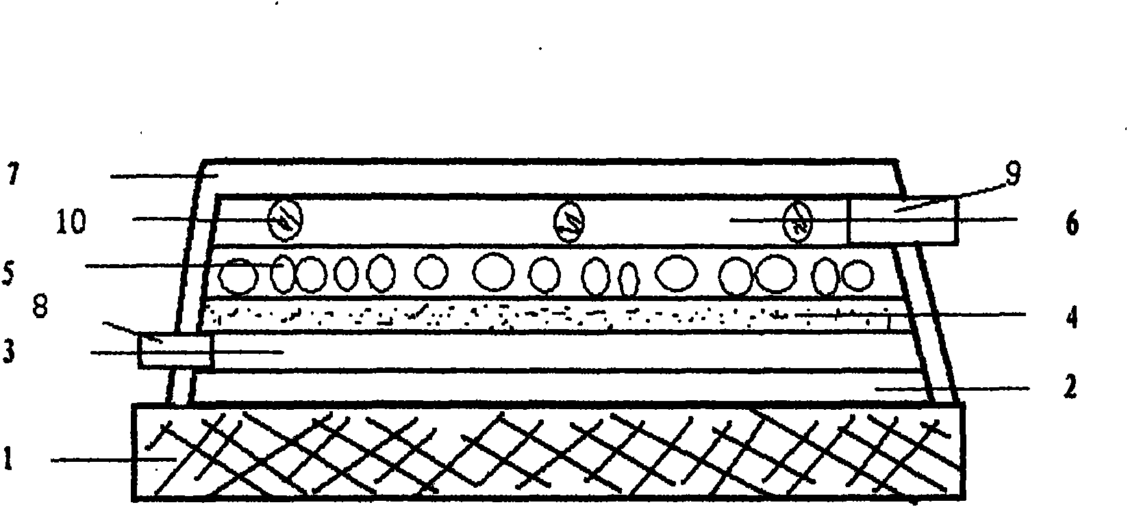
[0028] A continuous dense plane of silk (1). Surface screen printing waterproof fluorine paint protective layer substrate layer, thickness 0.5 microns; dry at room temperature. On the silver layer of the conductive material of the silk screen printing base, the thickness is 2 microns, and it is dried at room temperature.

[0029] Take 10 grams of BaTiO powder and add it to 10 grams of fluorine paint glue. After mixing, evenly screen-print on the surface of the waterproof layer with a thickness of 3 microns and dry at room temperature.

[0030] Take 15 grams of D513 type electroluminescent powder, mix it with 15 grams of fluorine paint colloid, and evenly screen-print it on the surface of the medium layer, with a thickness of 5-30 microns, and dry it at room temperature.

[0031] The transparent conductive layer is made of ITO with a thickness of 0.5 microns, sprayed and dried at a temperature of 40 degrees.

[0032] The material of the transparent outer protective layer is s...


PUM


Abstract

The invention provides an electroluminescence fabric which comprises a basic fabric (1), a protective layer lining layer (2) arranged on the surface of the basic fabric, a basic conductive material layer (3) arranged on the surface of the lining layer, a medium material layer (4) arranged on the surface of the conductive material layer, a luminescence layer (5) arranged on the outer surface of themedium layer and a transparent conductive material layer (6) arranged on the outer surface of the luminescence layer. The outer surface of the conductive layer uses a protective layer (7) to seal thelayers. An electroluminescence fabric device is a plane luminescence light source, is soft and folding can be cut, has uniform and silken light luminescence, favorable waterproofness, rich colors, and is applied to various dynamic luminescence clothing and advertisements.

Description

technical field [0001] The invention relates to a light-emitting display device in light-emitting physics, in particular to a planar light-emitting cloth device that uses an electric field to emit light. Background technique [0002] Electric (field) luminescent device (abbreviated as EL), its luminescent core is electroluminescent material, the material is mainly composed of II-VI luminescent material, and the luminescent center realizes composite luminescence through the energy provided by the electric field. The luminescent material is composed of 5 - Composed of 30 micron powder microcrystalline particles, there are a large number of luminescent line pairs inside the microcrystalline particles, which generate light under the action of a uniformly distributed high field. [0003] The existing electroluminescent planar light source devices mainly include: electroluminescent glass devices, electroluminescent plastic devices, and electroluminescent enamel devices. The above-...

Claims


Application Information

Patent Timeline
Patent Type & Authority Applications(China)
IPC IPC(8): H05B33/12H05B33/14H05B33/22H05B33/28H05B33/20
Inventor 耿树范边静宇费运启郑岩
Owner SHANGHAI KERUN PHOSPHOR TECH
Why Eureka
Try Eureka