Solar module serially connected in the front

A solar cell, series connection technology, used in energy conversion devices, sustainable manufacturing/processing, final product manufacturing, etc., can solve the problems of unrealization and high surface loss

Inactive Publication Date: 2010-02-10
FRAUNHOFER GESELLSCHAFT ZUR FOERDERUNG DER ANGEWANDTEN FORSCHUNG EV
View PDF0 Cites 13 Cited by
  • Summary
  • Abstract
  • Description
  • Claims
  • Application Information

AI Technical Summary

Problems solved by technology

Due to the relatively high surface losses, very efficient modules are not yet possible in this way

Method used


Image

  • Solar module serially connected in the front
  • Solar module serially connected in the front
  • Solar module serially connected in the front

Examples


Embodiment Construction

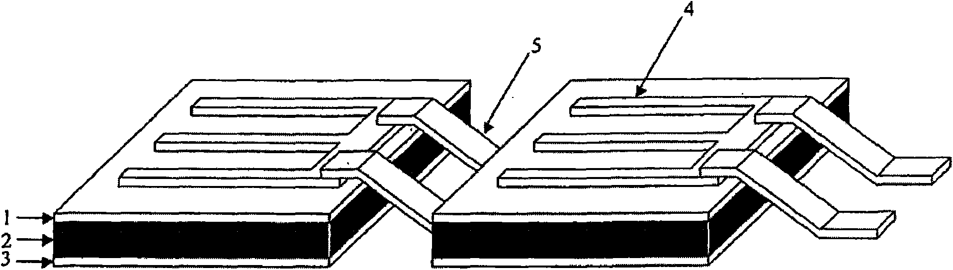
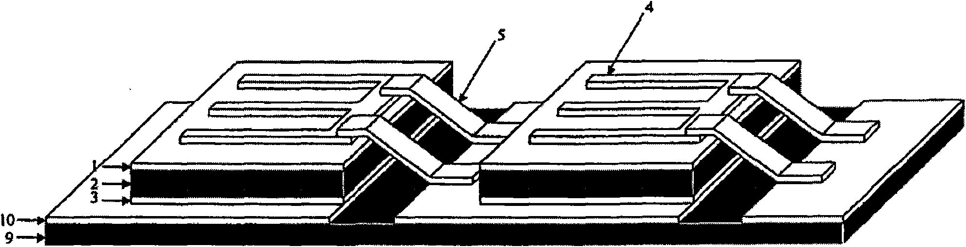
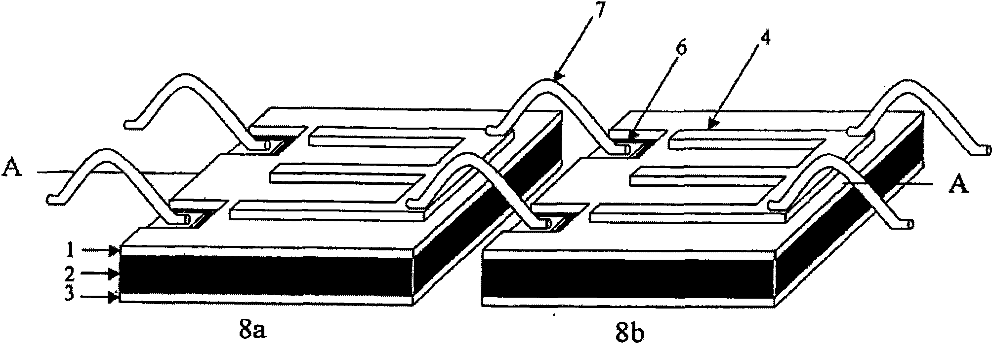
[0059] Figure 2 shows two solar cell elements 8a, 8b according to the invention and also shows that these two solar cell elements are electrically connected in series to form a solar module according to the invention. Figure 2a shows the situation in the form of a three-dimensional overall view, Figure 2b One of the solar cell elements (element 8a) according to the invention is shown in a cross-sectional view on the plane A-A, which is perpendicular to the plane of the semiconductor layers of the device and perpendicular to the axis described below, about which the respective The solar cell elements are arranged adjacent to each other at intervals (direction of electrical series connection). Figure 2c A top view of the device according to the invention perpendicular to the plane of the semiconductor layers is shown.

[0060] Each of the solar cell elements 8a, 8b according to the present invention comprises the following components: a supporting semiconductor layer 2 (here...


PUM


Abstract

The invention relates to a solar cell element comprising a semiconductor substrate layer (2) that has exactly one first dopant, a layer structure (1) which is disposed on the front side of the substrate layer (2), adjacent thereto, and has at least one dopant complementary to the first dopant, a rear metallization (3) which is arranged on the rear side of the substrate layer (2), adjacent to the substrate layer, said rear side lying across from the layer structure (1), and a first (4) and a second (6) front metallization. The first front metallization (4) electrically contacts the layer structure (1) while the second front metallization (6) is disposed on the front side of the substrate layer, adjacent to the substrate layer, and is electrically insulated from the first front metallizationand the layer structure (1).

Description

technical field [0001] The invention relates to a solar cell element suitable for being connected in series on the front side in a solar cell module, and also to a corresponding solar cell module. Furthermore, the invention relates to a method for the manufacture of corresponding solar cell elements and solar cell modules, and also to the use of corresponding solar cell elements and modules in concentrator installations. [0002] The invention is firstly applied in the field of high-concentration photoelectric systems (concentrator devices). Here, concave mirrors concentrate high-intensity sunlight onto relatively small module surfaces. For the situation where the light intensity is increased by a hundred times relative to normal sunlight, it is described here as a concentration ratio of 100 daylight. In this way, expensive solar cell surfaces can be replaced by relatively inexpensive mirror surfaces. At concentration ratios of several 100 suns, the use of solar cells made ...

Claims


Application Information

Patent Timeline
Patent Type & Authority Applications(China)
IPC IPC(8): H01L31/05H01L27/142H01L31/048H01L31/068H01L31/0687
CPCH01L31/052H01L27/142Y02E10/52Y02E10/544H01L31/0687H01L31/05H01L31/048H01L27/1421H01L31/0475B64G1/443H01L2224/48137H01L31/0504Y02E10/547Y02P70/50
Inventor 鲁地戈尔·劳克恩夫
Owner FRAUNHOFER GESELLSCHAFT ZUR FOERDERUNG DER ANGEWANDTEN FORSCHUNG EV
Why Eureka
Try Eureka