
Laser interference system used for measuring micro roll angle

一种激光干涉、光干涉的技术,应用在激光干涉系统领域,能够解决测量精度影响、不易实时测量、需要参考镜等问题,达到系统稳定、结构简单、分辨率高的效果

Inactive Publication Date: 2010-02-17
UNIV OF SHANGHAI FOR SCI & TECH
View PDF4 Cites 59 Cited by
  • Summary
  • Abstract
  • Description
  • Claims
  • Application Information

AI Technical Summary

Problems solved by technology

The measurement resolution of this type of method is very different with different length detection methods. For example, Ma Junshan et al. "Research on Optical Precision Measurement Technology of Roll Angle Error" in Acta Optics Sinica, 2000, 20(10): 1403-1406. Based on the principle that the reflected light intensity will change drastically when the angle changes near the critical angle, a differential precision angle sensor is designed to obtain a measurement repeatability accuracy of 0.05″, but a reference mirror is required and calibration is required, and the sensitivity of light intensity detection is affected by the light source and the influence of signal-to-noise ratio
In addition, the measurement accuracy of the two-point method (or three-point method) is affected by many factors, and it is time-consuming and laborious, so it is not easy to use in real-time measurement

Method used


Image

  • Laser interference system used for measuring micro roll angle
  • Laser interference system used for measuring micro roll angle
  • Laser interference system used for measuring micro roll angle

Examples


Embodiment Construction

[0035] The purpose of the present invention will be described in detail below with reference to the accompanying drawings.

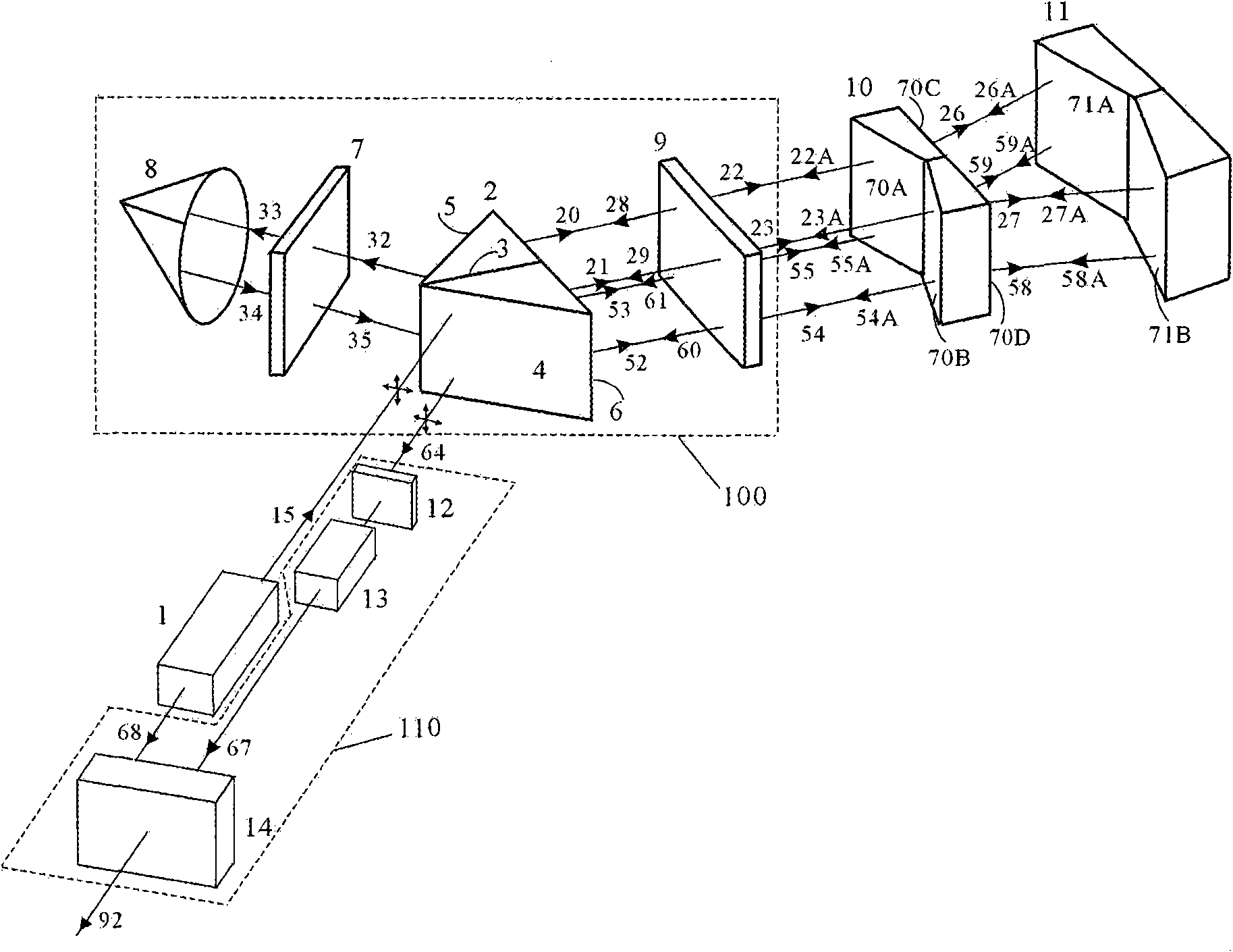
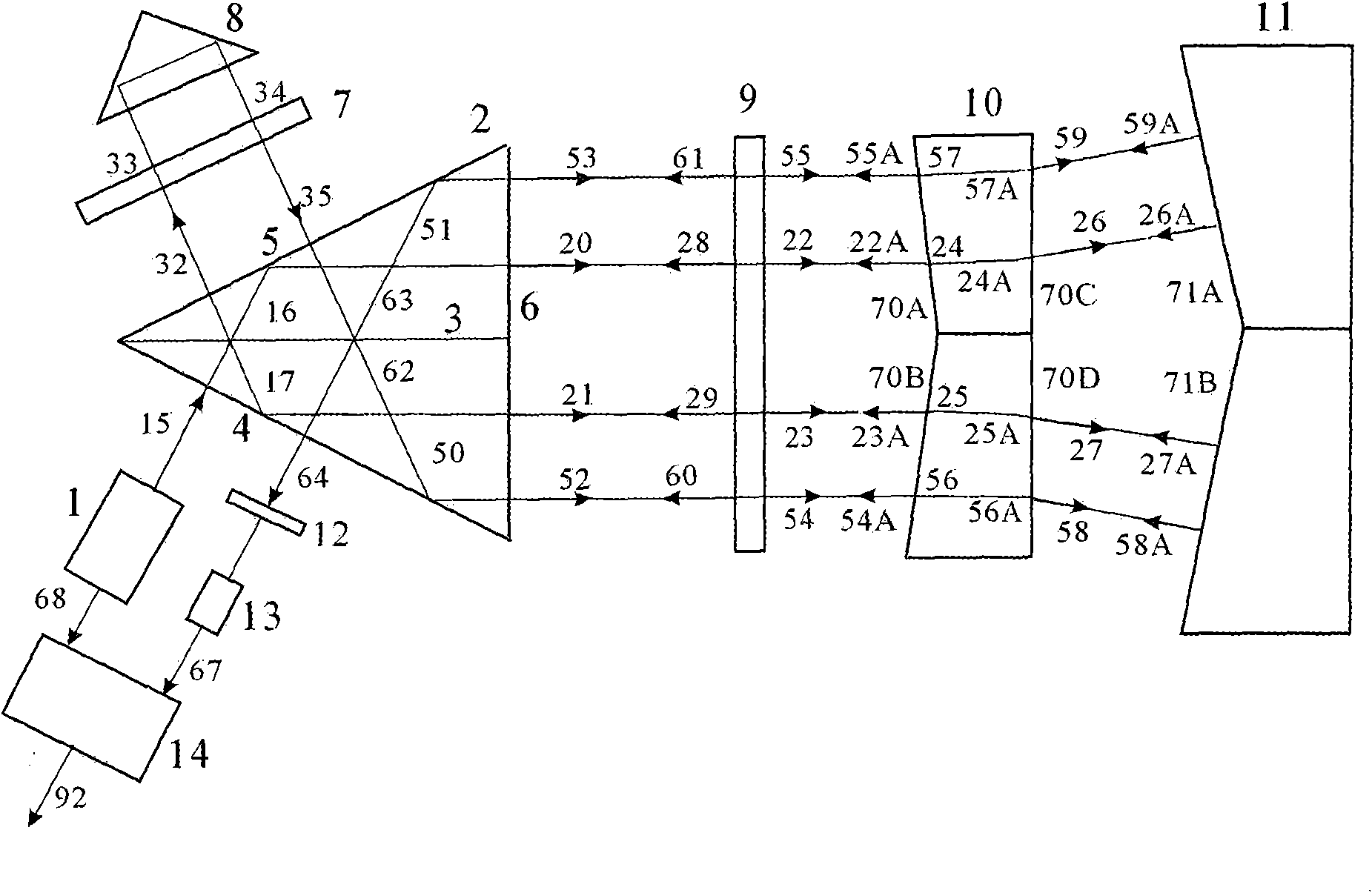
[0036] figure 1 It is a structural diagram of a laser interference system according to a preferred embodiment of the present invention, including a laser source 1 , an optical interference device 100 , a wedge prism 10 , a light reflection device 11 , and a phase detection device 110 .

[0037] The optical interference device 100 includes a dichroic prism 2 , a quarter wave plate 9 , a quarter wave plate 7 , and a corner cube 8 . The phase detection device includes a polarizer 12 , a photodetector 13 and a phase meter 14 .

[0038] The laser source 1 adopts a dual-frequency laser. On the one hand, the laser source 1 provides a frequency-stabilized incident beam to the beam splitter 2. The beam contains two components with different frequencies and linear polarization directions that are orthogonal to each other. At the same time, it also provides a phas...


PUM


Abstract

The invention relates to a laser interference system used for measuring a micro roll angle surrounding the linear displacement direction. The laser interference system comprises a laser source, a polarized light-splitting prism, two quarter wave plates, a corner prism, a wedge-angle prism, a wedge-angle reflecting mirror, a polarizer, a photoelectric detector and a phase meter; the laser source generates incident beams with stable frequency and provides a stable reference signal source simultaneously; the incident beams pass through the wedge-angle prism twice under the actions of the light-splitting prism, the quarter wave plates and the corner prism, and are correspondingly reflected by the wedge-angle reflecting mirror twice and sent out by the polarized light-splitting prism; by the interference of the polarizer, the photoelectric detector receives and generates an electric measuring signal, and the micro roll angle of the wedge-angle reflecting mirror fixedly connected with a measured piece can be measured by phase comparison between the phase meter and an electric reference signal. The invention has the advantages of simple structure and high measurement precision, and can bewidely applied to geometrical precision measurement and metering base creation in the fields of military projects, spaceflights, digital control machine tools, and the like.

Description

technical field [0001] The invention relates to laser precision measurement technology, in particular to a laser interference system for measuring the micro-rotation angle around the line displacement direction. Background technique [0002] In high-tech fields such as military industry, aerospace, and CNC machine tools, precision reference measurement and precise measurement of geometric quantities play a very important role, especially the measurement technology of micro-rotation angle around the direction of displacement movement, which has attracted more and more attention. The traditional interferometric method of micro-rotation angle around the displacement motion axis is relatively complicated. The key technology is to use a flat reflector with the same length as the stroke. This plane reflector with the same length as the stroke is generally installed on the moving DUT and moves accordingly. The light emitted by the light source shoots to the plane reflector and is ...

Claims


Application Information

Patent Timeline
Patent Type & Authority Applications(China)
IPC IPC(8): G01B11/26G02B5/04G02B27/28G02B5/08G02B1/10
CPCG01B11/26G01B9/02019G01B2290/15G01B9/02007G01B9/02003G01B9/02018G01B2290/70G01B9/02
Inventor 侯文玫赵宪斌张运波
Owner UNIV OF SHANGHAI FOR SCI & TECH
Learn More