
Device and method for adjusting and monitoring line polarization energy

A linear polarization and laser energy technology, applied in the field of online polarization, can solve problems such as energy inconsistency, difference in total output energy of the light source, and increase in users

Inactive Publication Date: 2010-02-17
SHANGHAI INST OF OPTICS & FINE MECHANICS CHINESE ACAD OF SCI
View PDF0 Cites 5 Cited by
  • Summary
  • Abstract
  • Description
  • Claims
  • Application Information

AI Technical Summary

Problems solved by technology

For a period of time, the output of the light source is approximately stable, but long-term use will inevitably lead to a large difference between the total output energy of the light source and the energy at the time of initial use
Testing the total energy of the linearly polarized light before each experiment increases the workload of the user. If each measurement is ignored, the information on the reduction of the total energy of the light source is often not obtained in time, resulting in a discrepancy between the actual energy used and the actual energy required. Experiments have no reference value

Method used


Image

  • Device and method for adjusting and monitoring line polarization energy

Examples


Embodiment Construction

[0021] The present invention will be further described below in conjunction with the embodiments and accompanying drawings, but the protection scope of the present invention should not be limited thereby.

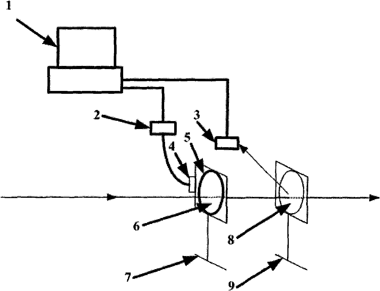
[0022] see figure 1 . figure 1 It is a structural schematic diagram of a device for adjusting and monitoring linearly polarized light energy. It can be seen from the figure that the device for adjusting and monitoring linearly polarized light energy in the present invention consists of a computer 1, a stepper motor driver 2, an energy meter 3, a stepper motor 4, a half-wave plate 6, a turntable optical adjustment frame 7, and a polarization beam splitter Mirror 8 and polarization beam splitter adjustment frame 9 are composed, and its positional relationship is as follows: described polarization beam splitter 8 is installed on the described polarization beam splitter adjustment frame 9, and described half-wave plate 6 is fixed on the described On the turntable 5 of the tur...


PUM


Abstract

The invention relates to a device and a method for adjusting and monitoring line polarization energy. The device comprises a computer, a stepping motor driver, an energy meter, a stepping motor, a half-wave piece, a turntable optical adjusting bracket, a polarization beam-splitting mirror and an adjusting bracket of the polarization beam-splitting mirror. The invention has the characteristics of simple structure, low cost and convenient use and can ensure that the line polarization energy in a light path stably conforms to the actual requirement.

Description

technical field [0001] The invention relates to linearly polarized light, in particular to a device and method for adjusting and monitoring the energy of linearly polarized light. Background technique [0002] Linearly polarized light is often used in laboratories. The traditional method of adjusting the output linearly polarized light energy by changing the control parameters of the linearly polarized light source not only affects the service life of the light source, but also the output of the light source cannot reach a stable state immediately after each parameter adjustment. More and more users tend to use computer-controlled combination systems including half-wave plates and polarizers to adjust their energy during online polarized light transmission. This method of automatically adjusting the energy in the optical path often depends on the total energy of the linearly polarized light. For a period of time, the output of the light source is approximately stable, but ...

Claims


Application Information

Patent Timeline
Patent Type & Authority Applications(China)
IPC IPC(8): G02B26/02G05D25/02
Inventor 刘晓凤赵元安王建永李大伟李笑邵建达
Owner SHANGHAI INST OF OPTICS & FINE MECHANICS CHINESE ACAD OF SCI
Learn More