Distribution protection method and distribution protection device

A power distribution protection and protection value technology, applied in the direction of emergency protection circuit devices, electrical components, etc., can solve problems such as misjudgment, easy burnout, and large constraints by devices, so as to reduce misoperation, prolong overcurrent judgment time, The effect of reducing the possibility of damage

Active Publication Date: 2010-02-17
HUAWEI DIGITAL POWER TECH CO LTD
View PDF0 Cites 11 Cited by
  • Summary
  • Abstract
  • Description
  • Claims
  • Application Information

AI Technical Summary

Problems solved by technology

[0005] In the prior art, the overcurrent protection is realized by using the current limiting method of the linear working area characteristic of the semiconductor device, which is greatly restricted by the device. It usually takes hundreds of us to ms to make a comparison judgment until the shutdown is realized), and it is easy to burn out after a long time, so it is necessary to quickly determine the protection action to protect the circuit, which will also bring the risk of misjudgment at the same time, that is, if it is too long The longer the over-current judgment time, the higher the possibility of damage to the semiconductor device, and the smaller the possibility of misjudgment; on the contrary, the shorter the over-current judgment time, the smaller the possibility of semiconductor damage, but the possibility of misjudgment is smaller. The higher the probability, in other words, the existing technical solution has the problem of the mutual restriction of the accuracy of overcurrent judgment and the possibility of semiconductor device being damaged

Method used


Image

  • Distribution protection method and distribution protection device
  • Distribution protection method and distribution protection device
  • Distribution protection method and distribution protection device

Examples


Embodiment 3

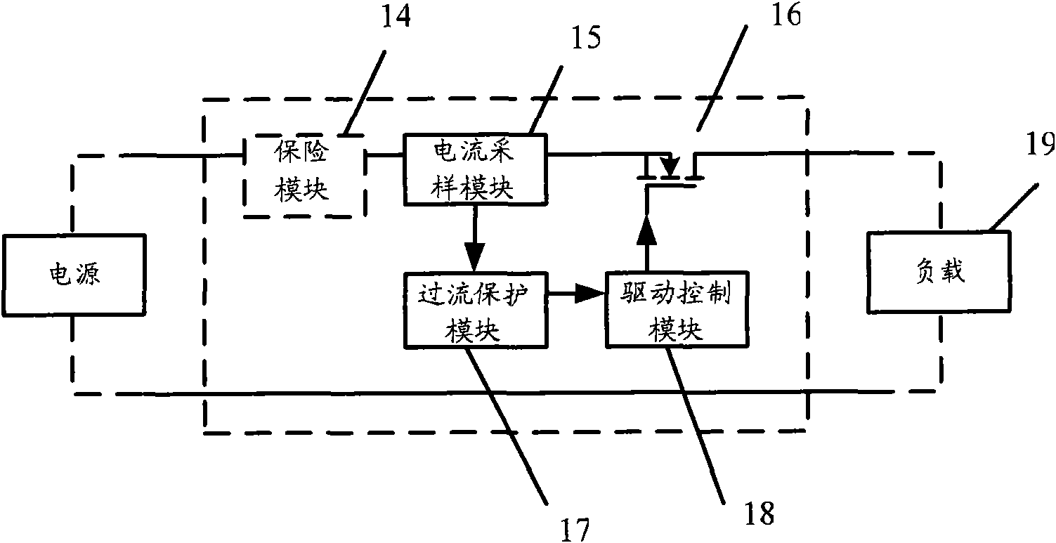
[0053] Figure 4 It is a schematic structural diagram of a power distribution protection device including a protected circuit according to Embodiment 3 of the present invention.

[0054] Such as Figure 4 As shown in the figure, the protected circuit includes a semiconductor switching device Q, an inductor L, a freewheeling diode D, a sampling resistor R, an input capacitor Cin and an output capacitor Cout. It should be noted that the protected circuit may also include multiple parallel-connected freewheeling diodes D and / or multiple parallel-connected semiconductor switching devices Q. The semiconductor switch device Q in the embodiment of the present invention is exemplified by a MOSFET, but not limited thereto.

[0055] Wherein, the source S of the semiconductor switching device Q may be connected in series with a sampling resistor R, and the sampling resistor R is connected in parallel with an input capacitor Cin, and the drain D of the semiconductor switching device Q m...

Embodiment 4

[0089] The difference between the fourth embodiment and the third embodiment mainly lies in the addition of the function of local or remote control on the basis of digital control.

[0090] Figure 10 It is a schematic structural diagram of a power distribution protection device including a protected circuit according to Embodiment 4 of the present invention.

[0091] Such as Figure 10 As shown in the figure, the protected circuit includes a semiconductor switching device Q, an inductor L, a freewheeling diode D, a sampling resistor R, an input capacitor Cin and an output capacitor Cout. It should be noted that a plurality of freewheeling diodes D and semiconductor switching devices Q connected in parallel may also be included.

[0092] Figure 10 The upper half of the circuit with Figure 4 same. Figure 10 In the lower part of , it includes an analog control loop module 101 , a digital control circuit module 102 , a local interface module 103 , a remote interface modul...


PUM


Abstract

The invention discloses a distribution protection method and a distribution protection device. The method comprises the following steps: sampling a protected circuit and acquiring a sampling current value, wherein the protected circuit comprises a semiconductor switching device, an inductor and a fly-wheel diode; the semiconductor switching device is connected in series with the inductor; and thefly-wheel diode is jointly connected between the semiconductor switching device and the inductor; comparing the sampling current value with a limit protection value; calculating a cumulative energy value of the sampling current value when the sampling current value is larger than a rated current value, but smaller than or equal to the limit protection value; switching off the semiconductor switching device by a driving signal if the cumulative energy value is larger than a preset energy value; and switching off the semiconductor switching device by the driving signal when the sampling currentvalue is larger than the limit protection value. The technical scheme improves the accuracy of overcurrent judgment and reduces the possibility of damaging semiconductor devices.

Description

technical field [0001] The invention relates to the technical field of power distribution protection, in particular to a power distribution protection method and a power distribution protection device. Background technique [0002] In power distribution protection circuits, circuit breakers are often used. Traditional circuit breakers include thermal circuit breakers and electromagnetic circuit breakers. In recent years, a new circuit breaker, that is, a semiconductor switching device (such as a Metal-Oxide-Semiconductor-Field-Effect Transistor (MOSFET, Metal-Oxide-Semiconductor-Filed-Effect Transistor)) has emerged. [0003] figure 1 It is a schematic diagram of power distribution protection in the prior art. Such as figure 1 As shown, it mainly includes: an insurance module 14 , a current sampling module 15 , a field effect transistor MOSFET 16 , an overcurrent protection module 17 , a drive control module 18 , and a load 19 . Wherein, the MOSFET 16 is connected in se...

Claims


Application Information

Patent Timeline
Patent Type & Authority Applications(China)
IPC IPC(8): H02H7/22
Inventor 田帆
Owner HUAWEI DIGITAL POWER TECH CO LTD
Why Eureka
Try Eureka