This helps you quickly interpret patents by identifying the three key elements:
Problems solved by technology
Method used
Benefits of technology
Problems solved by technology
[0015] The present invention is to solve the above-mentioned problem in the supply equipment of high-purity water using the conventional reaction furnace for water generation, that is, to respond to the amount of water supplied by increasing the size (or capacity) of the reaction furnace for water generation Due to the increased requirements of the platinum-coated catalyst membrane, the increase in the size of the reactor for moisture generation is limited due to the structural aspects such as the durability of the platinum-coated catalyst film, so there is a problem of certain restrictions; When supplying the mixed gas G from the mixed gas split supply device to a plurality of production reactors operating in parallel to respond to the increase in the amount of water supplied, not only the equipment cost and management cost of the mixed gas G split supply device will be incurred The increase of height, and the problem of needing a large installation space; and other problems, the main purpose of the invention is to provide a method for parallel operation of the reaction furnaces for water generation, which does not require a complicated flow distribution device for the mixed gas G. An orifice member with a predetermined inner diameter is provided in the center of the mixed gas supply line of each moisture generating reactor operating in parallel, and a predetermined amount can be supplied inexpensively and accurately to each moisture generating reactor operating in parallel with a simple mechanism. The mixed gas G, which can easily respond to the increase in the amount of moisture generation
Method used
Image
Click on the blue label to locate the original text in one second.
Reading with bidirectional positioning of images and text.
Examples
Embodiment approach
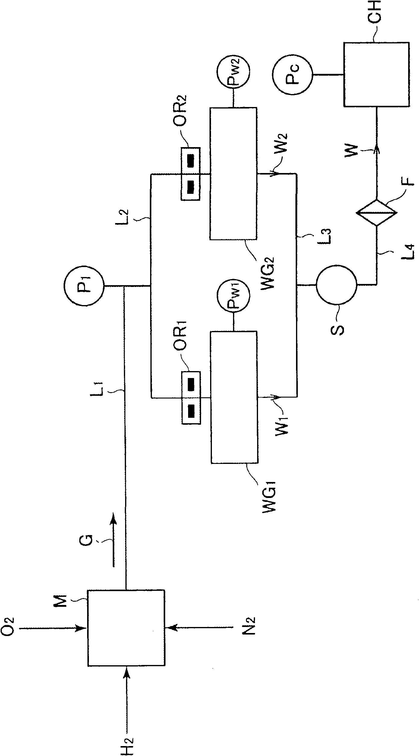
[0065] figure 1 1st Embodiment of this invention is shown, and the case where moisture W is supplied to process chamber CH of normal pressure using two reaction furnaces WG1 and WG2 for moisture generation is shown.
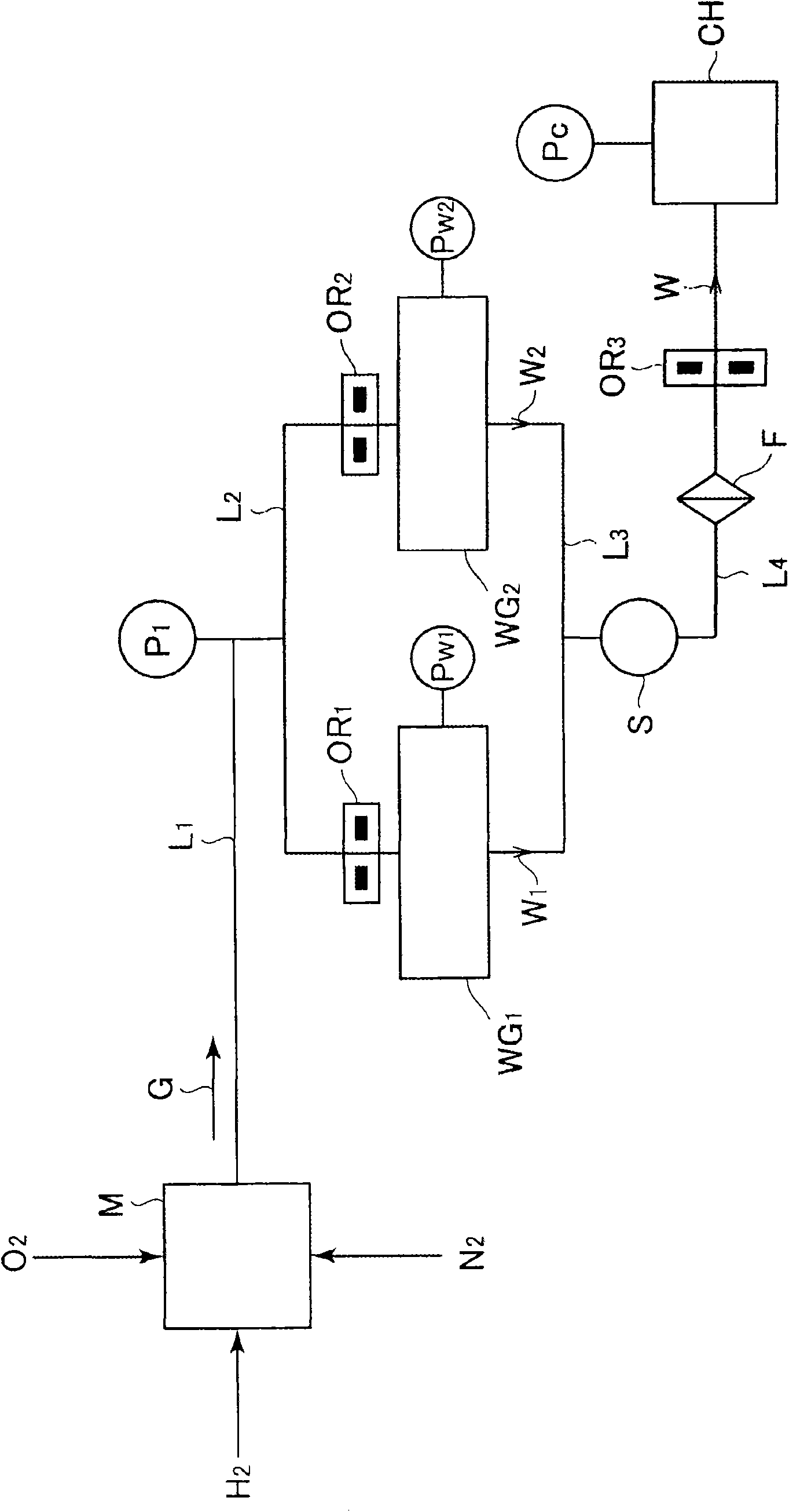
[0066] exist figure 1 Medium, H 2 is hydrogen, O 2 is oxygen, N 2 is nitrogen, M is H 2 and O 2 The gas mixer, G is the mixed gas, WG 1 、WG 2 It is a reaction furnace for moisture generation, OR 1 , OR 2 is the hole part, S is H 2 Sensor, F is filter, CH is process chamber, P 1 、PW 1 、PW 2 ,P C is the manometer, W 1 , W 2 , W is moisture, L 1 , L 2 , L 3 , L 4 It is piping.
[0067] The above-mentioned reaction furnaces for generating water WG1 and WG2 use two reaction furnaces for generating water of the same specification, which are made of stainless steel with an outer diameter of about 180mmφ and a thickness of about 37mm. layer coating.
[0068] In addition, in this embodiment, two moisture generating reactors of the same specificatio...
Embodiment 1
[0093] Figure 5 It uses two reaction furnaces for water generation WG 1 、WG 2 A system diagram when 17 SLM of moisture gas W is supplied to the chamber CH used at normal pressure (760 Torr). In addition, Table 5 shows the assumption that the Figure 5 The system diagram in the hole component OR 1 , OR 2 The pressure on the upstream side of the orifice part calculated from the flow rate Q and the cross-sectional area S when the critical condition between upstream and downstream is established.
[0094] In addition, formula (1) shows the calculation formula of the flow rate Q,
[0095] [number 1]
[0096] Q = SP H T H · C ′ · ( F . F . ) . . . . . ...
Embodiment 2
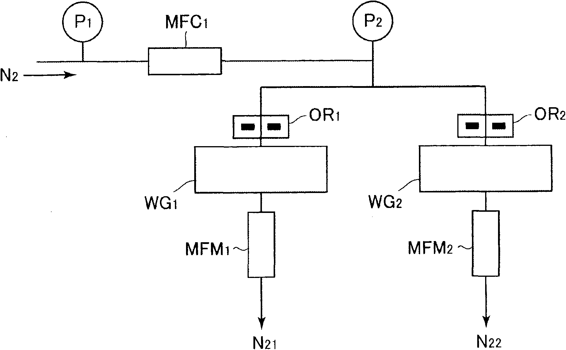
[0101] in with the above Figure 5 In the same system diagram, calculate the H corresponding to the water generated by 17SLM 2 and O 2 The upstream side (pipe upstream side) and downstream side (orifice part OR) of the mass flow meter MFC when the mixed gas G flows 1 , OR 2 The pressure P on the upstream side of 1 ,P 2 , Equation (2) and Equation (3) represent the calculation formula.
[0102] [number 2]
[0103] Q=C(P 1 -P 2 )……(2)
[0104] [number 3]
[0105] C = π 8 η a 4 l ( P 1 + P 2 2 ) . . . . . . ( 3 ) ...
PUM
Property
Measurement
Unit
diameter
aaaaa
aaaaa
diameter
aaaaa
aaaaa
diameter
aaaaa
aaaaa
Abstract
In the event of meeting demands for an increase of the amount of high-purity water fed through parallel run of multiple reaction furnaces for moisture generation, simplification of mixed gas (raw gas)distributor and marked reduction of equipment cost are attained by realizing of the distribution supply of H2 and O2 mixed gas with the use of very simple orifice. Accordingly, there is provided a method of parallel run of reaction furnaces for moisture generation, comprising disposing an orifice with bore of given diameter on the mixed gas entrance side of each of parallelly connected multiple reaction furnaces for moisture generation so that not only is hydrogen / oxygen mixed gas (G) from a mixing unit fed through the orifice to each of the reaction furnaces for moisture generation but alsothe moistures generated by the individual reaction furnaces for moisture generation are joined together and fed to high-purity water using apparatus.
Description
technical field [0001] The present invention relates to a method for parallel operation of reaction furnaces for generating moisture, which is used, for example, in semiconductor manufacturing equipment and chemical manufacturing equipment. By inserting a hole member having an appropriate diameter into each raw materialgas supply line of the reaction furnace for moisture generation, it is possible to stably operate the reaction furnaces for moisture generation in parallel with a predetermined amount of water generation. Background technique [0002] In the additional treatment of siliconoxide film by the moisture oxidation method of semiconductor manufacturing equipment, etc., it is necessary to supply high-purity water, and usually, such as Figure 8 As shown, the required high-purity water is supplied using a reaction furnace for water generation. [0003] That is, the reaction furnace for generating moisture is as disclosed in International Publication No. WO97 / 28085 an...
Claims
Application Information
Patent Timeline
Application Date:The date an application was filed.
Publication Date:The date a patent or application was officially published.
First Publication Date:The earliest publication date of a patent with the same application number.
Issue Date:Publication date of the patent grant document.
PCT Entry Date:The Entry date of PCT National Phase.
Estimated Expiry Date:The statutory expiry date of a patent right according to the Patent Law, and it is the longest term of protection that the patent right can achieve without the termination of the patent right due to other reasons(Term extension factor has been taken into account ).
Invalid Date:Actual expiry date is based on effective date or publication date of legal transaction data of invalid patent.

