Transparent glass with heating coating

A window glass and coating technology, applied in the field of transparent window glass, can solve problems such as opacity

Inactive Publication Date: 2010-02-17
SAINT-GOBAIN GLASS FRANCE
View PDF13 Cites 42 Cited by
  • Summary
  • Abstract
  • Description
  • Claims
  • Application Information

AI Technical Summary

Problems solved by technology

Of course the busbars are mostly

Method used


Image

  • Transparent glass with heating coating
  • Transparent glass with heating coating

Examples


Embodiment Construction

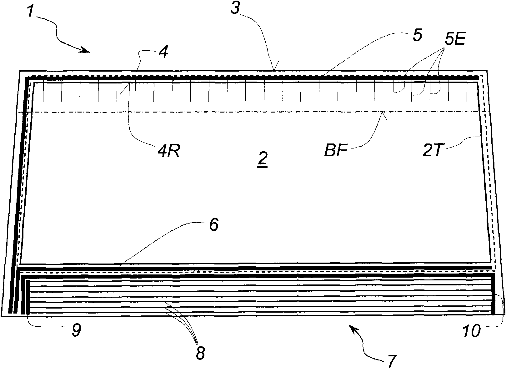
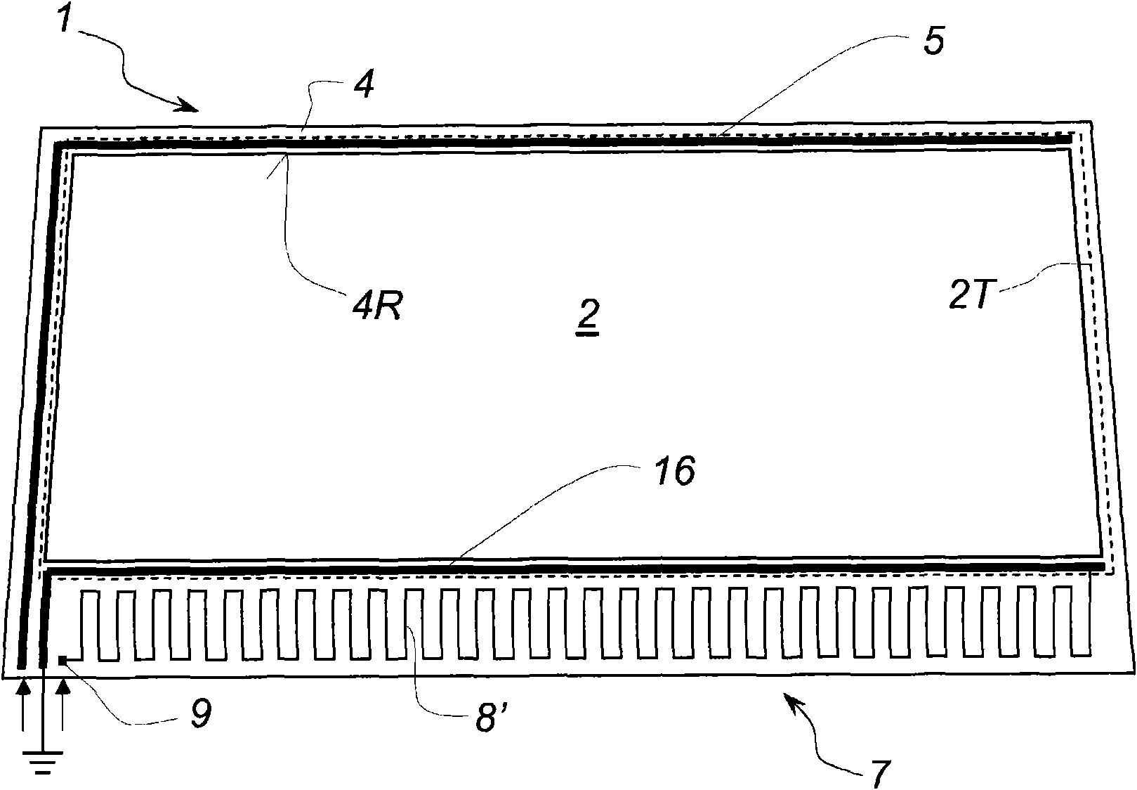
[0034] according to figure 1 , an electrically conductive and completely transparent coating 2 is incorporated in a substantially trapezoidal heated composite glazing 1 in a manner known per se.

[0035] The dashed line marked 2T indicates that on all sides the outer edge of the continuously covered surface tapers slightly inwards with respect to the outer edge 3 of the composite glazing 1 or that the edge band is spaced from the entire coating. In this way, electrical insulation from the outside is obtained on the one hand, and the coating is protected from corrosion from the outer edges on the other hand. By masking the substrate during deposition of the coating, removing the coating along the edge of the glazing, or also by drawing a perimeter dividing line through the coating along the outer edge of the glazing, a shrinkage 2T of the outer edge can be caused, which satisfies Insulation and protection against corrosion.

[0036] The coating itself preferably and in a mann...


PUM

PropertyMeasurementUnit
Surface resistanceaaaaaaaaaa

Abstract

The invention relates to a transparent glass (1) having an electrically heating coating (2) extending on a large portion of the glass surface, in particular in the field of vision (4R), and electrically connected to at least two collecting conductors having a low electrical resistance (5, 6) so that, after applying an electric supply voltage to the collecting conductors, an electric current flowsin the heating field defined by the coating. According to the invention, a heating member (7) is provided with low electric-resistance conducting members (8, 8') such as wires and/or printed conducting tracks in an area of the surface that is not heated by the coating (2) and preferably located at the edge of the transparent glass (1) on the same face as the coating (2). It is thus possible to obtain an independent heating of said area of the surface while shortening the current paths in the coating with a relatively high electric resistance.

Description

technical field [0001] The invention relates to a transparent pane with an electrically heated coating, which has the features of the preamble of claim 1 . Background technique [0002] In particular for vehicle windshields, there is a strong demand in the market for heating modes, wherein the heating itself should also be as visually imperceptible or as uncomfortable as possible. There is therefore an increasing demand for transparent heating coatings for window panes. [0003] A common problem with weakly light-absorbing heating coatings is that their sheet resistance remains relatively high, which in any case requires a high supply voltage for large panes or long current paths to be heated, which The supply voltage is in any case greater than the usual on-board voltage in the vehicle. If it is desired to reduce the sheet resistance, since the conductive layer must be thicker, this results in a reduction in the transmission of visible light in currently known stacked sys...

Claims


Application Information

Patent Timeline
IPC IPC(8): H05B3/84H05B3/86
CPCH05B2203/016B32B17/10036H05B2203/017H05B2203/031H05B3/84H05B3/86B32B17/10183H05B2203/013
Inventor A·布兰查德G·沙尔M·莫勒
Owner SAINT-GOBAIN GLASS FRANCE
Why Eureka
Try Eureka