Cam type centering clamping chuck

A clamping chuck and cam type technology, applied in the field of mechanical processing, can solve the problems of low centering accuracy, high manufacturing cost, limited clamping force, etc., and achieve the effect of simple structure of parts, low cost and high precision

Inactive Publication Date: 2010-02-24
SICHUAN AEROSPACE LONG MARCH EQUIP MFG CO LTD
View PDF0 Cites 18 Cited by
  • Summary
  • Abstract
  • Description
  • Claims
  • Application Information

AI Technical Summary

Problems solved by technology

The existing centering clamping devices include coil wire type, wedge type, lever type and helical tooth type. Some of them have low centering accuracy, some have limited clamping force, and some have complex structures and high manufacturing costs.

Method used


Image

  • Cam type centering clamping chuck
  • Cam type centering clamping chuck
  • Cam type centering clamping chuck

Examples


Embodiment Construction

[0028] The present invention will be further described below in conjunction with the accompanying drawings and embodiments.

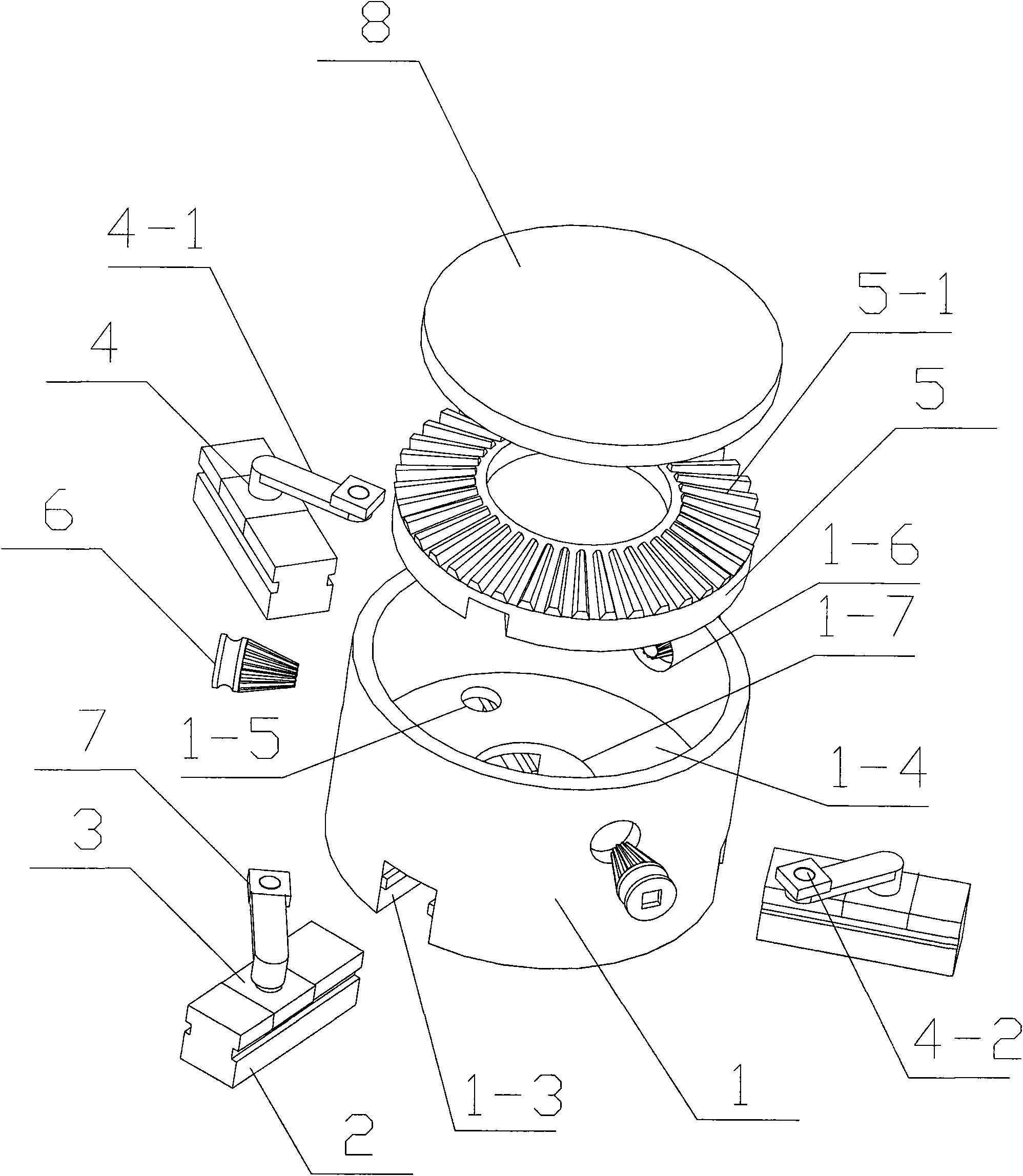
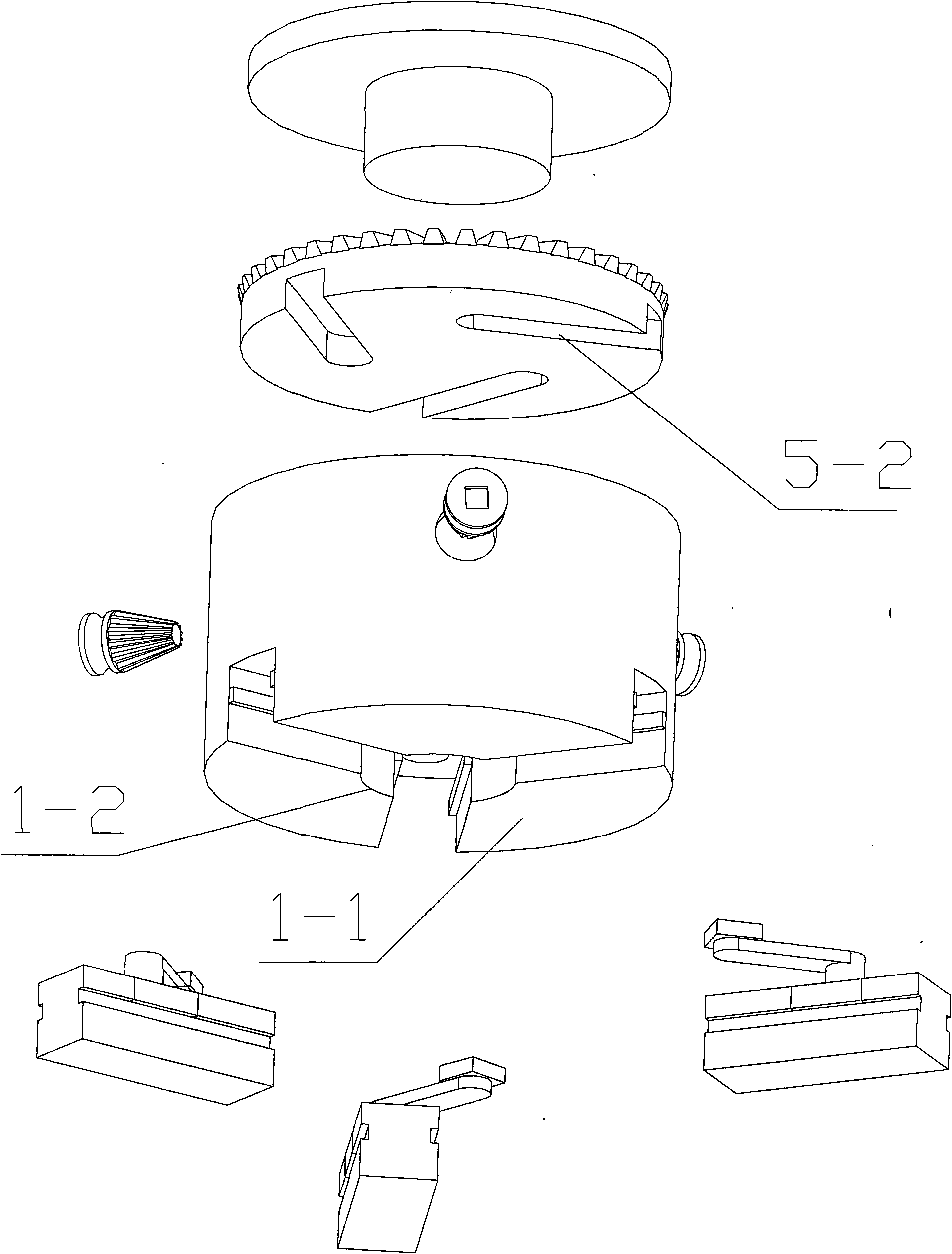
[0029] Cam-type centering clamping chuck, including the chuck body 1, and also includes three jaws 2, three square sliders 3, three eccentric cams 4, three clamping blocks 7, toothed disc 5 and three small cones Gear 6; disc body 1 is a cylindrical groove body, and its base plate 1-1 is provided with a central hole 1-2, and base plate 1-1 is provided with three equally divided radial chute 1-3; chuck body 1 is provided with A partition 1-4 is provided with three equally divided partition through holes 1-5 and a partition center hole 1-7, and the upper wall of the chuck body 1 is provided with three wall holes 1-6 equally divided along the circumference The claw 2 cooperates with the chute 1-3, the inner end surface of the claw 2 is provided with a square slot, the square slider 3 is embedded in it, and the square slider 3 is provided with a slider hole;...


PUM


Abstract

The invention discloses a cam type centering clamping chuck, which belongs to the technical field of mechanical processing. The cam type centering clamping chuck comprises a chuck body, and is characterized by comprising three claws, three square slide blocks, three eccentric cams, three blocks, a fluted disc and three small bevel gears; the chuck body is a cylindrical groove, the bottom of the eccentric cam is provided with a lever which extends along the side direction, and the end of the lever is provided with a cylindrical pin; the upper end plane of the fluted disc is provided with the bevel gear, the lower end plane is provided with three round-head straight flutes which are distributed uniformly; and the small bevel gears are engaged with the bevel gear. The cam type centering clamping chuck has the advantages of high precision, low cost, simple structure of the components, benefit design, compact overall structure, small volume, light abrasion and long service lifetime. The camtype centering clamping chuck is suitable for loading the revolving body component for lathing, turn milling and center machining.

Description

Technical field [0001] The invention relates to a machining fixture, in particular to a device for centering and clamping a workpiece, and belongs to the technical field of machining. Background technique [0002] At present, when the workpiece is machined, especially when the rotary workpiece is cut, in order to ensure the machining accuracy of the workpiece, it is first necessary to center and clamp the workpiece with a centering clamping device. The existing centering clamping devices include coil wire type, wedge type, lever type and helical tooth type, some of them have low centering accuracy, some have limited clamping force, some have complex structure and high manufacturing cost. Contents of the invention [0003] In order to overcome the above-mentioned shortcomings of the existing centering clamping device, the present invention provides a chuck for self-centering clamping of the workpiece by utilizing the centrifugal force when the workpiece rotates. [0004] T...

Claims


Application Information

Patent Timeline
Patent Type & Authority Applications(China)
IPC IPC(8): B23B31/171
Inventor 杨振宇
Owner SICHUAN AEROSPACE LONG MARCH EQUIP MFG CO LTD
Why Eureka
Try Eureka