Protective atmosphere vacuum sintering furnace with high temperature of 1800 DEG C

A vacuum sintering furnace, high temperature protection technology, applied in furnaces, muffle furnaces, cooking furnaces, etc., can solve problems such as low yield of sintered products, volatilization of silicon vapor, and easily damaged equipment, and achieve insulation and sealing problems and improve Equipment reliability and energy-saving effects

Inactive Publication Date: 2010-02-24
SHENYANG HENGJIN VACUUM TECH
View PDF0 Cites 30 Cited by
  • Summary
  • Abstract
  • Description
  • Claims
  • Application Information

AI Technical Summary

Problems solved by technology

[0002] Sic ceramics is a new type of material with superior performance, and its application field is expanding rapidly. The high-temperature sintering furnace, an important equipment for manufacturing sic ceramic devices, has a high sintering temperature of Sic ceramics, most of which need to be at 1450-1750 degrees, and there is serious silicon vapor volatilization during the sintering process. , the problem of easily damaged equipment, and the yield of sintered products is also low

Method used


Image

  • Protective atmosphere vacuum sintering furnace with high temperature of 1800 DEG C
  • Protective atmosphere vacuum sintering furnace with high temperature of 1800 DEG C
  • Protective atmosphere vacuum sintering furnace with high temperature of 1800 DEG C

Examples


Embodiment Construction

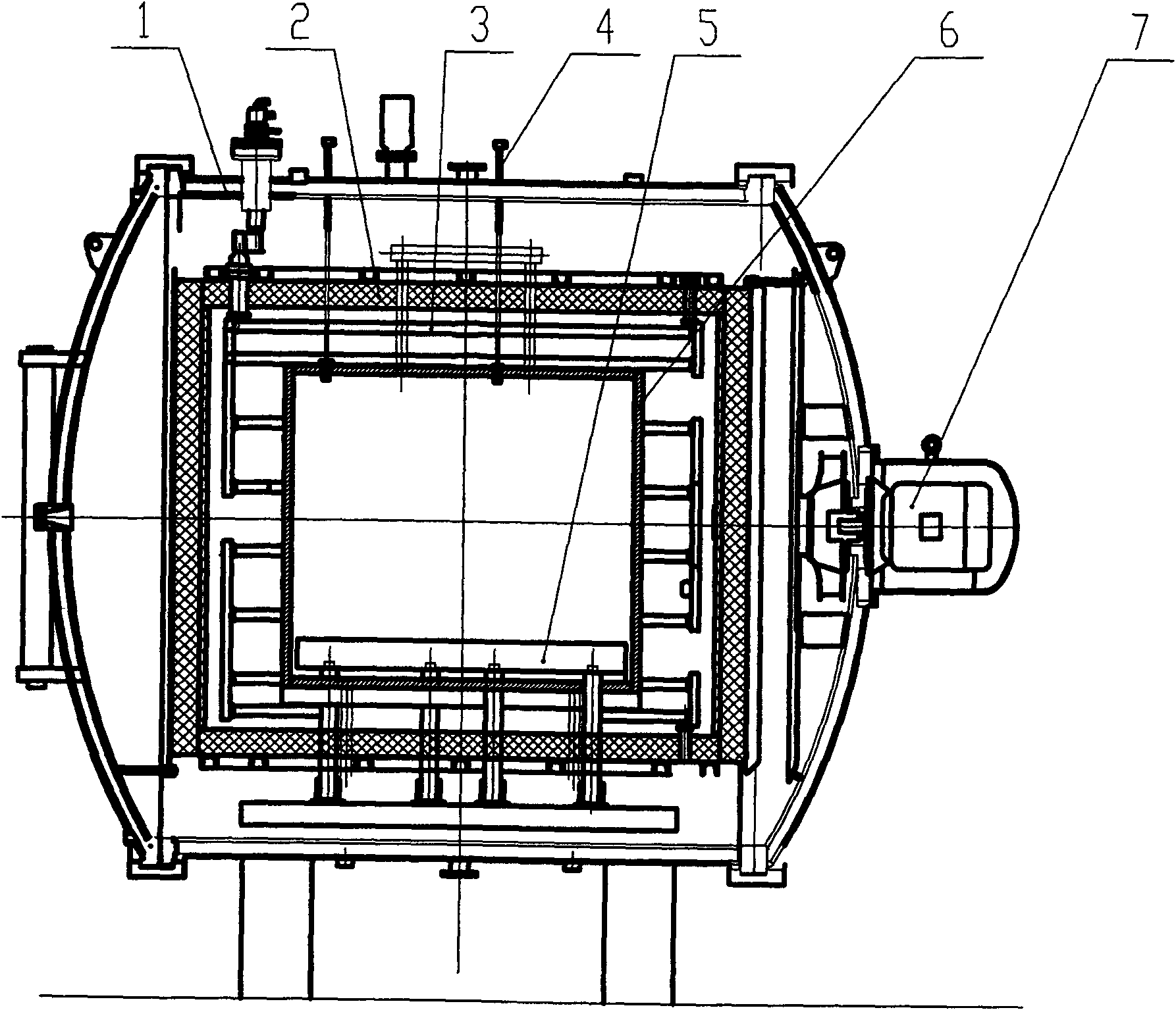
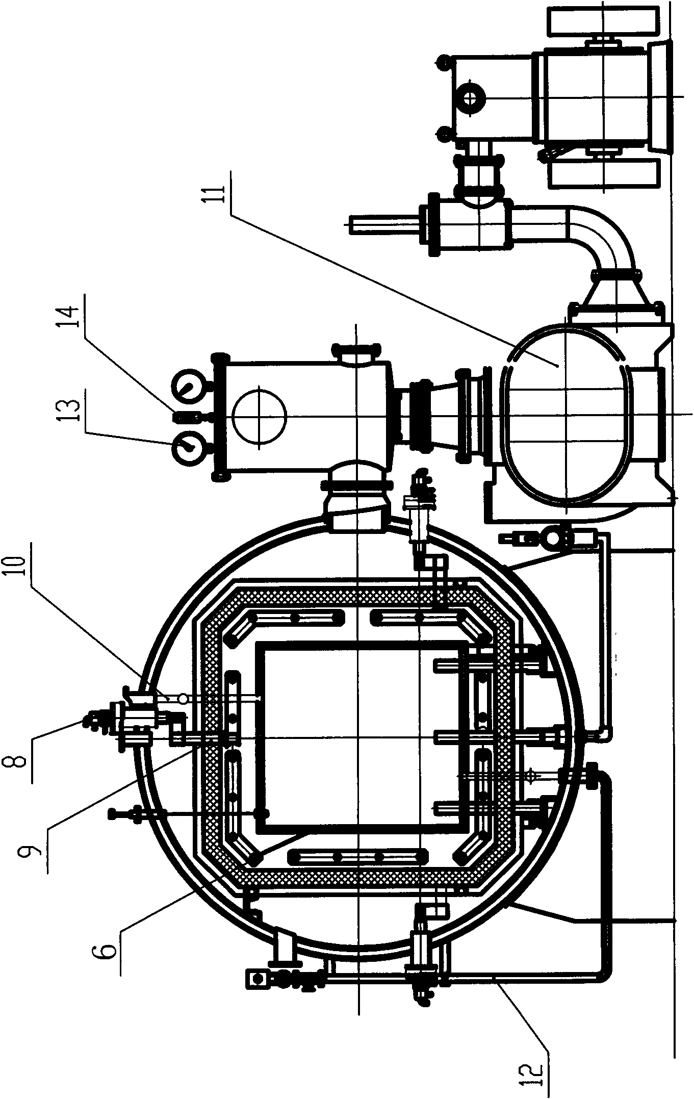
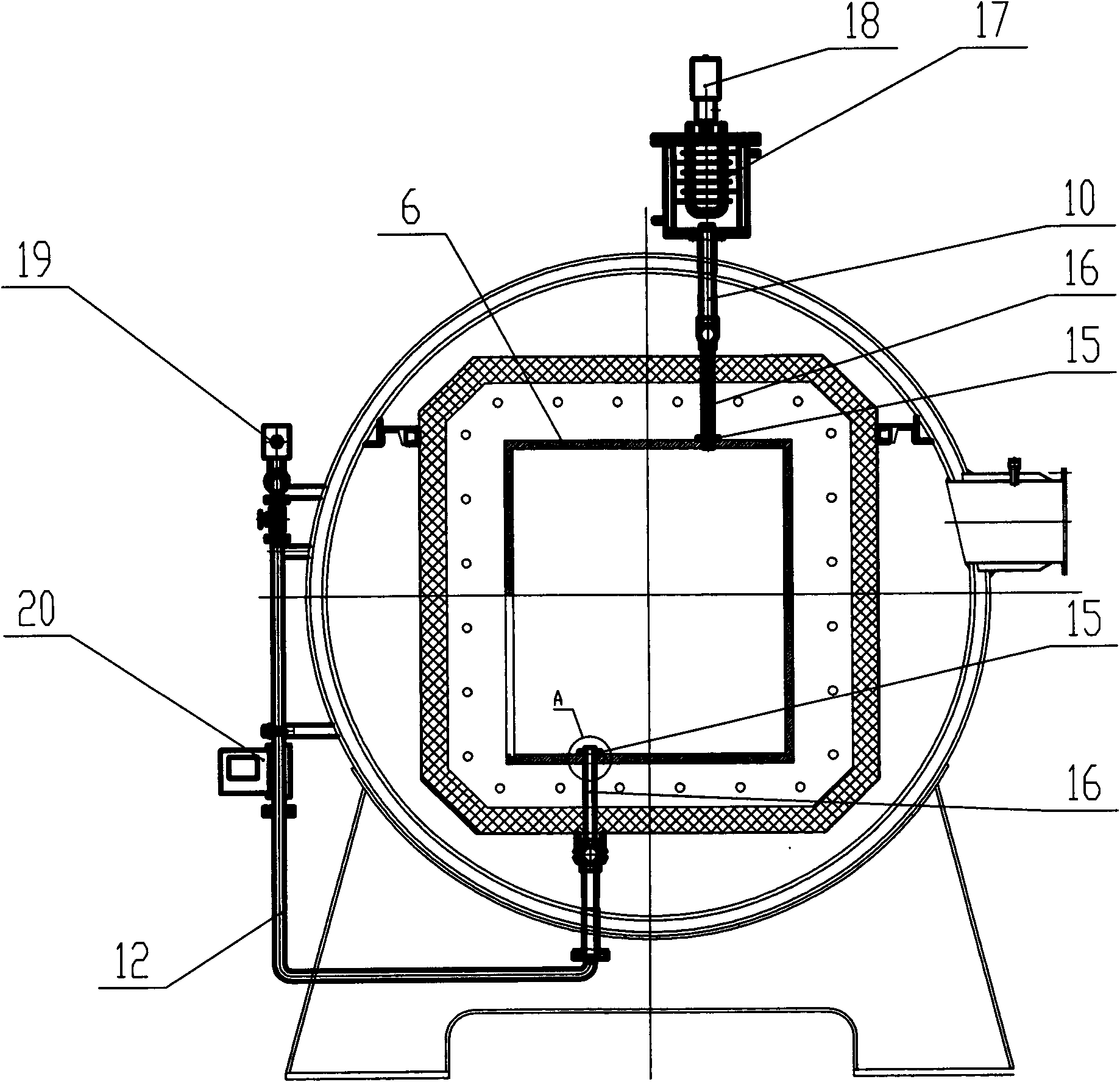
[0019] 1800 degree high temperature protective atmosphere vacuum sintering furnace of the present invention, see figure 1 , figure 2 : The furnace shell 1 is a cylinder, installed axially and horizontally, and the furnace end is opened. It is characterized in that the furnace shell 1 is equipped with a square heating chamber 2, and the graphite heater 3 is fixed on the four walls of the heating chamber 2. Inside the heater 3 Sealing box 6 is installed again, and the base plate of support rack 5 is parallelly fixed in housing 1, and its vertical column passes heating chamber 2, sealing box 6, and horizontal plate is installed in sealing box 6 at the column upper end. The air intake duct 10 and the exhaust duct 12 of the Unicom sealed box 6 pass through the heating chamber 2 and the upper and lower walls of the sealed box 6 through the graphite tube 16 to communicate with the box, see image 3 The thermocouple 4 for measuring temperature is fixed on the housing 1, and its temp...


PUM


Abstract

The invention discloses a protective atmosphere vacuum sintering furnace with high temperature of 1800 DEG C. A control system is connected with an electronically-controlled execution component arranged in an apparatus, a graphite sealing box is arranged in a heating chamber, an air inlet pipeline and an exhaust pipeline of a high-temperature vacuum sintering furnace are connected with the graphite sealing box. The protective atmosphere vacuum sintering furnace is characterized in that the furnace has two techniques of atmosphere sintering and vacuum sintering, and a function conversion measurement is actualized by a control program; a furnace shell is provided with a thermoelectric couple and a copper electrode; the part of a shell column body is provided with a pipe joint communicated with an evacuation unit of a vacuum system; and a square heating chamber is arranged in the furnace shell, heaters are fixed on four walls in the heating chamber, and the heater is internally provided with a sealing box and a support material frame; and the air inlet pipeline and the exhaust pipeline communicated with the sealing box passes through an upper wall and a lower wall of the heating chamber and the sealing box through a graphite pipe to communicate with the inside of the sealing box, one end of the furnace shell is provided with a gas circulating cooling blower, an inner wall of the sealing box is provided with the thermoelectric couple and the copper electrode, and the copper electrode is connected with the heater through a graphite electrode. A volatile substance sealed in the sealing box can not disperse during vacuum sintering, thereby effectively preventing the volatile substance from polluting and damaging the heater, and simultaneously achieving the effect of enabling the protective gas to take the volatile substance away to protect furnace materials, and improving the utilization ratio of the protective gas.

Description

technical field [0001] The invention belongs to manufacturing equipment of special ceramics and is used for vacuum sintering of sic ceramic devices. Background technique [0002] Sic ceramics is a new type of material with superior performance, and its application field is expanding rapidly. The high-temperature sintering furnace is an important equipment for manufacturing sic ceramic devices. The sintering temperature of Sic ceramics is relatively high, and most of them need to be at 1450-1750 degrees. During the sintering process, there is serious silicon vapor volatilization. , the problem of easily damaged equipment, and the yield of sintered products is also low. The sintering furnace of the present invention aims at the problems existing in the sic sintering process, and carries out a new design on the structure of the sintering chamber and the sintering process, so as to solve the problem of silicon vapor pollution, improve the reliability of the equipment, and help i...

Claims


Application Information

Patent Timeline
Patent Type & Authority Applications(China)
IPC IPC(8): F27B5/04F27B5/06F27B5/14F27B5/16F27B5/18F27D11/10C04B35/565C04B35/64
Inventor 杨建川赵建业曲绍芬石岩张晓东高光伟党艳敏
Owner SHENYANG HENGJIN VACUUM TECH
Why Eureka
Try Eureka