Testing device for quickly detecting flow property parameters of air passage of internal combustion engine

A flow performance and test device technology, applied in the direction of internal combustion engine testing, etc., can solve the problems of reducing the test accuracy of the airway steady flow test bench, increasing the cost, noise, etc.

Active Publication Date: 2010-02-24
TIANJIN UNIV
View PDF0 Cites 17 Cited by
  • Summary
  • Abstract
  • Description
  • Claims
  • Application Information

AI Technical Summary

Problems solved by technology

In order to improve efficiency, two sets of pipelines and flow test instruments are needed. In addition to increasing the cost, the difference bet...

Method used


Image

  • Testing device for quickly detecting flow property parameters of air passage of internal combustion engine
  • Testing device for quickly detecting flow property parameters of air passage of internal combustion engine
  • Testing device for quickly detecting flow property parameters of air passage of internal combustion engine

Examples


Embodiment 1

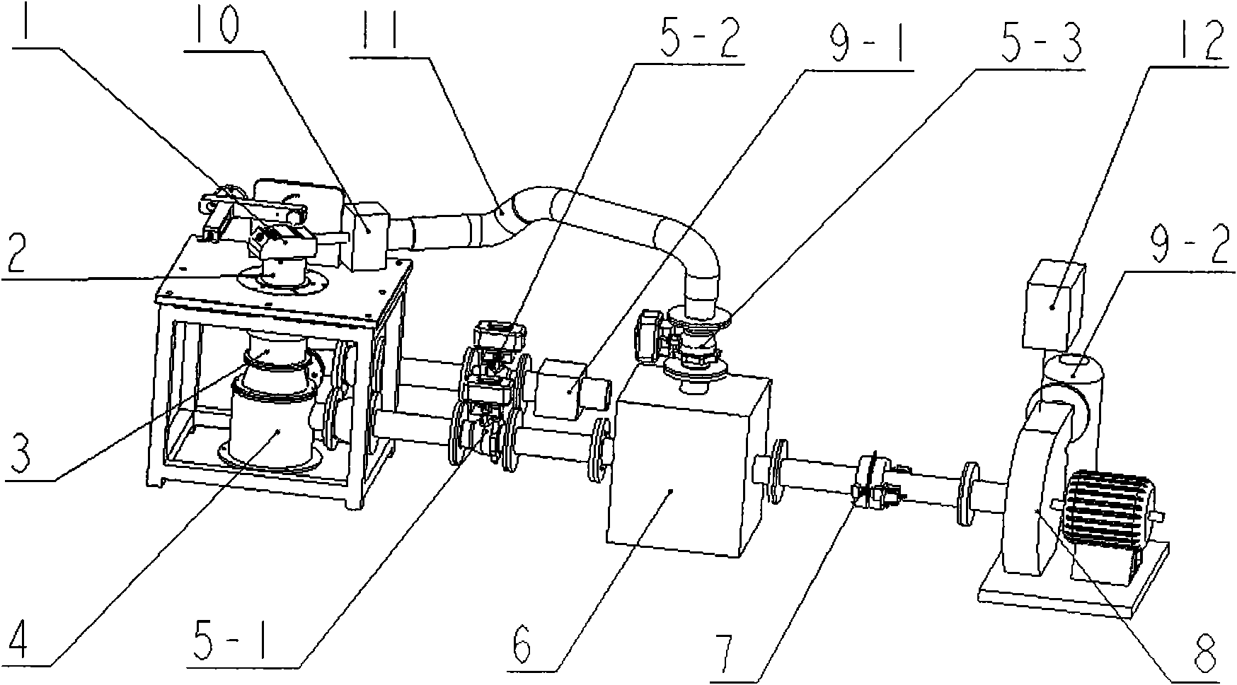
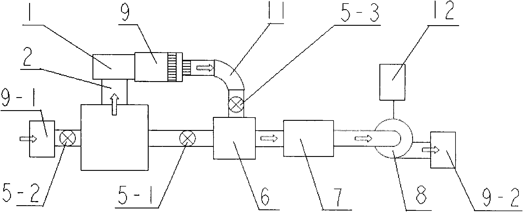
[0012] Exhaust duct steady flow test. The maximum valve lift is 10mm, and the bore is 100mm. Place the cylinder head under test on the cylinder liner. The first electric ball valve is closed, the second and third electric ball valves are opened, the valve lift is adjusted to 1mm, the intake valve lift is always 0mm, and the airway pressure difference is set to 5Kpa. Start the fan, the air flow direction is as follows figure 2 As shown by the arrow, through the first air filter→pressure regulator barrel→momentum meter→cylinder liner→air passage (exhaust passage)→airflow comber→hose→pressure regulator box→flow meter→induced fan→second air filter. There is a pressure tap at the place where the top surface of the cylinder liner is 1.75 times lower than the bore (175mm downward from the top surface). The difference between the atmospheric pressure and the pressure here is the airway pressure difference. The frequency adjusts the speed of the induced draft fan to maintain the a...

Embodiment 2

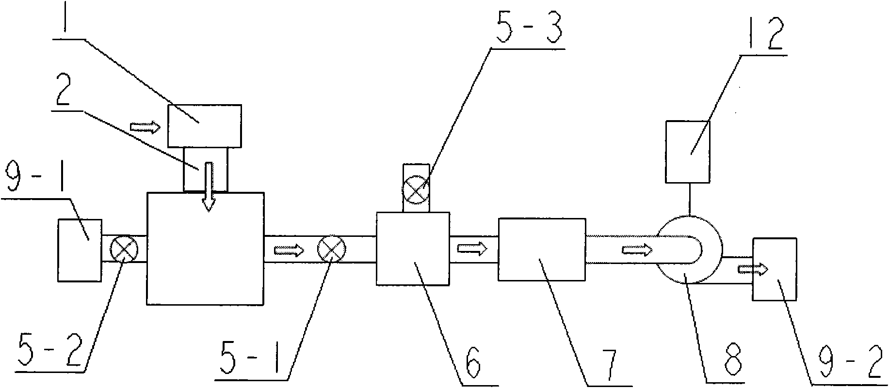
[0014] Inlet steady flow test. On the basis of Example 1, the test speed is further improved. The foregoing conditions are the same as in Embodiment 1, the intake valve lift is adjusted to 10 mm, and the exhaust valve lift is always 0 mm. Start the induced draft fan, the air flow direction is as follows image 3 As shown by the arrow, through the air duct (intake duct)→cylinder liner→momentum meter→pressure regulator tank→pressure regulator box→flow meter→induced fan→the second air filter. The airway pressure difference is set to 5Kpa under the valve lift of 10mm, and the air flow in the cylinder liner is always in a fully developed turbulent state. Then, the computer controls the frequency converter to adjust the speed of the induced draft fan so that the airway pressure difference is 5Kpa. When the pressure is stable Then measure the flow coefficient and eddy current intensity, then change the valve lift to 9mm, keep the frequency converter unchanged, the flow section of t...


PUM


Abstract

The invention relates to a device for quickly detecting flow property parameters of an air passage of a cylinder cover of an internal combustion engine, which is characterized in that a testing air passage is arranged above a cylinder sleeve, and the center of the cylinder sleeve is coaxial with the center of a momentum meter; the lower end of the momentum meter is connected with a pressure stabilizing barrel which is provided with two channels, wherein one channel is sequentially connected with an electrical ball valve, a pressure stabilizing box, a flow meter and a draught fan, and the otherchannel of the pressure stabilizing barrel is sequentially connected with a second electrical ball valve and a first air filter; the exhaust end of the testing air passage is connected with an air flow carding machine, a third electrical ball valve is arranged above the pressure stabilizing box and is communicated with the air flow carding machine through a flexible tube, and the air exhaust sideof the draught fan is connected with a second air filter; and the rotating speed of the draught fan is controlled by a frequency converter. The testing process of the whole test only needs 3-5 minutes. The invention has the characteristics of reducing the cost of the testing equipment and reducing the test noise on the basis of improving the testing precision, and can be used for instantly detecting cylinder covers of engines in production lines.

Description

technical field [0001] The invention belongs to the measurement of performance parameters of an internal combustion engine, and in particular relates to a device for quickly detecting flow performance parameters of an air passage of a cylinder head of an internal combustion engine. technical background [0002] Flow coefficient, swirl intensity, tumble intensity and other flow characteristic parameters are important parameters to evaluate the performance of the intake and exhaust passages of internal combustion engines. The current airway steady-state flow test process is to adjust the valve lift to provide a stable pressure difference before and after the airway, and then conduct a steady-state flow test. However, when doing the steady flow test of different valve lifts, since the change of the valve lift will lead to the change of the flow section of the air passage, the same air volume, the pressure difference between the front and rear of the air passage will change, and...

Claims


Application Information

Patent Timeline
IPC IPC(8): G01M15/05
Inventor 王天友刘书亮鲁祯
Owner TIANJIN UNIV
Why Eureka
Try Eureka