
Cooling experiment system of supersonic speed air film

A film cooling and experimental system technology, which is applied in the testing of measuring devices, instruments, machines/structural components, etc., can solve the problems of incapable of supersonic film cooling technology experimental research, limited ability of thermal environment simulation, etc., and achieve high automation Level, the effect of accurate experimental data

Inactive Publication Date: 2010-02-24
BEIHANG UNIV
View PDF0 Cites 11 Cited by
  • Summary
  • Abstract
  • Description
  • Claims
  • Application Information

AI Technical Summary

Problems solved by technology

[0005] On the one hand, the existing experimental system has limited ability to simulate the thermal environment; on the other hand, it can only carry out the influence of the slot structure on the cooling effect, and cannot carry out systematic experimental research on the supersonic film cooling technology.

Method used


Image

  • Cooling experiment system of supersonic speed air film
  • Cooling experiment system of supersonic speed air film
  • Cooling experiment system of supersonic speed air film

Examples


Embodiment Construction

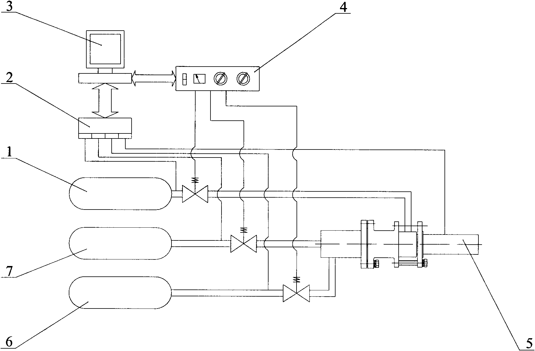
[0020] Supersonic film cooling experimental system, such as figure 1 As shown, it consists of a hydrogen supply system 7, an oxygen supply system 6, an air nitrogen supply system 1, an experiment section 5, a data acquisition device 2, a valve driving device 4, a computer 3 and experiment software.

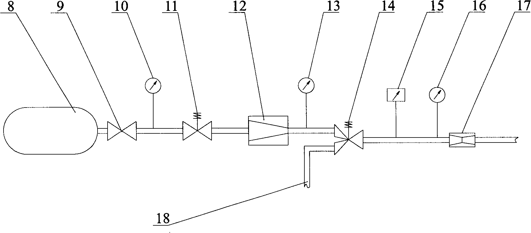
[0021] Hydrogen supply systems such as figure 2 As shown, by the high-pressure hydrogen storage tank 8, the hydrogen high-pressure hand valve 9, the hydrogen pre-valve 11, the hydrogen pressure reducer 12, the hydrogen solenoid valve 14, the hydrogen sonic nozzle 17, the nitrogen interface 18, the temperature sensor 15 and the pressure sensor 10, 13, 16 and so on. The high-pressure hydrogen storage tank 8 stores high-pressure hydrogen with a pressure of about 10 MPa. The hydrogen high-pressure hand valve 9 is the main switch of the gas source. When the hydrogen high-pressure hand valve 9 is opened, the high-pressure hydrogen reaches the inlet of the hydrogen pre-valve 11. The h...


PUM


Abstract

A cooling experiment system of a supersonic speed air film is mainly used for experiment research of supersonic speed air film cooling technology, wherein the effect of supersonic speed air film cooling caused by cooling jet current mach number, incidence angle, and side direction inclined angle can be researched on the system. A small size fuel gas generator takes hydrogen and oxygen as burning media to generate fuel gas at the temperature of 2000 K, and the fuel gas is accelerated to mach number 2 via a Laval nozzle. The outlet of the Laval nozzle is connected with a jet current generator and an experiment tube, and the air for cooling forms a beam of supersonic speed jet current through the jet current generator to be sprayed into the experiment tube for forming a beam of air film covered on the surface of the experiment tube. The back wall of the experiment tube is welded with 25 K type thermoelectric couples for measuring the wall temperature distribution covered by the air film.The signals of thermoelectric couple and other sensors are sent to a computer via a data collection device, and the experiment software processes and displays the signals. The experiment software sends the control instruction and controls to turn on or off each valve of system via a valve drive device.

Description

【Technical field】 [0001] The invention relates to the heat protection technology of the outer surface of high-speed aircraft in the atmosphere such as missiles and the inner surface of rocket engine, and is used for the experimental research of supersonic air film cooling technology. 【Background technique】 [0002] When high-speed aircraft such as missiles fly in the atmosphere, the outer surface of the nose cone can reach a temperature above 2000K due to aerodynamic heating. Since the structural materials of the missile cannot withstand such a high temperature, thermal protection measures must be taken for the outer surface of the missile. . The inner surface of the liquid rocket engine is exposed to high-temperature gas with a temperature of 3000K, and thermal protection measures must be taken for it. Supersonic film cooling technology is one of the feasible thermal protection measures. [0003] The principle of supersonic film cooling technology is to inject a layer of ...

Claims


Application Information

Patent Timeline
IPC IPC(8): G01M19/00G01M99/00
Inventor 孙冰张佳郑力铭
Owner BEIHANG UNIV
Learn More