
Free space optical communication device based on passive optical network (PON)

A passive optical network and free space technology, applied in free space transmission, electromagnetic wave transmission system, electrical components, etc., can solve problems such as inapplicable PON transmission protocol

Inactive Publication Date: 2010-02-24
朱万华
View PDF0 Cites 24 Cited by
  • Summary
  • Abstract
  • Description
  • Claims
  • Application Information

AI Technical Summary

Problems solved by technology

[0013] It can be seen that there is a clear difference between the PON transmission system and the SDH system. They are two completely different transmission protocols. The original FSO applied to the SDH framework is not suitable for the PON transmission protocol.

Method used


Image

  • Free space optical communication device based on passive optical network (PON)
  • Free space optical communication device based on passive optical network (PON)
  • Free space optical communication device based on passive optical network (PON)

Examples


Embodiment Construction

[0058] The specific implementation of the device will be described in detail below in conjunction with the accompanying drawings.

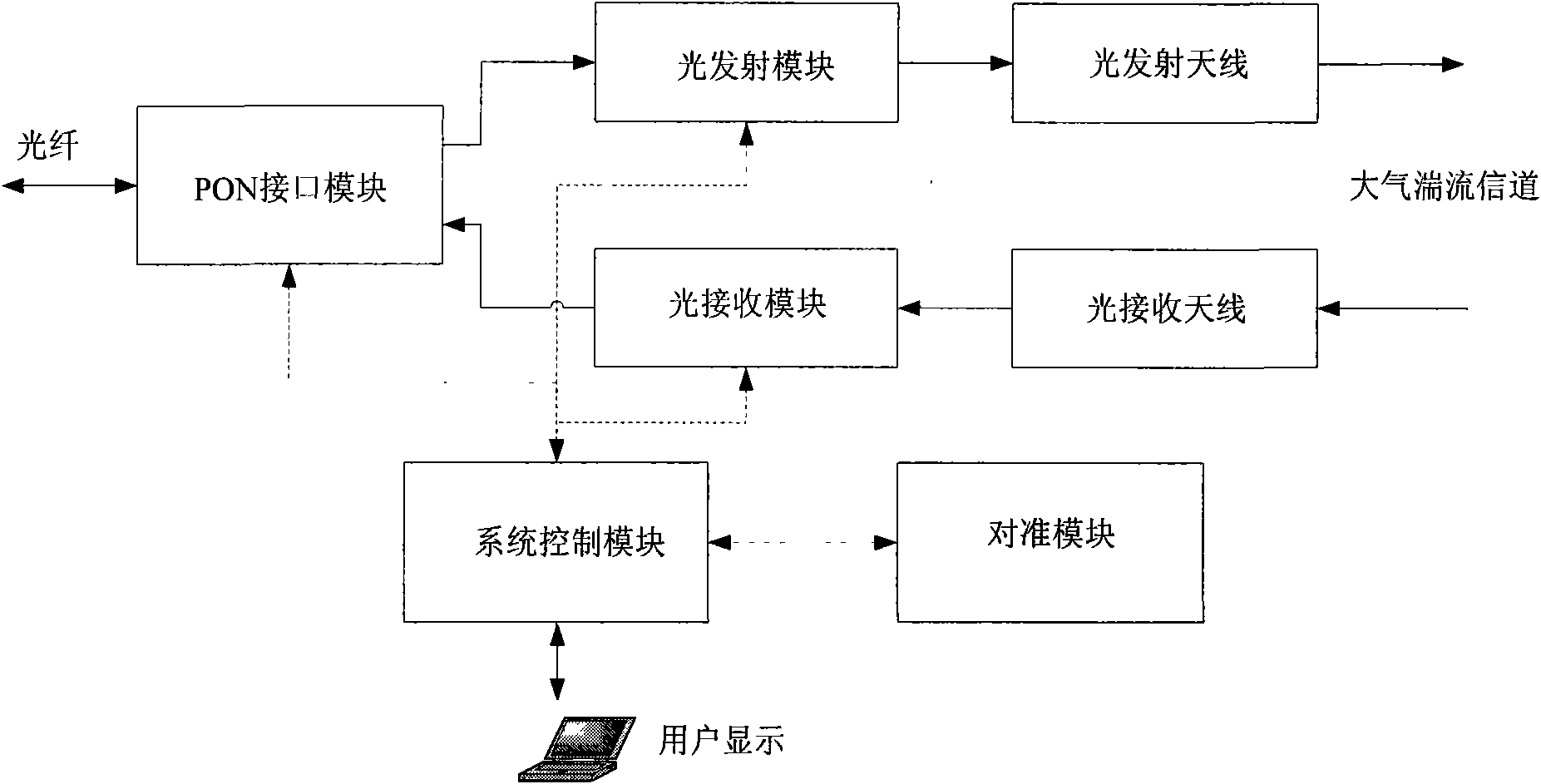
[0059] figure 1 It is a schematic diagram of the application of the device. After the signal from the PON device is processed by the interface module, it is converted into an electrical signal, and the laser is driven by the optical transmission module. The optical signal from another terminal in the space is received by the four-way optical receiving antenna, and the optical signal is coupled to the photoelectric conversion device in the optical receiving module through the four-in-one coupling optical fiber to convert the optical signal into an electrical signal and send it to the interface module for transmission to PON networks such as figure 2 shown.

[0060] The design and function of each part will be described in detail below:

[0061] PON interface module

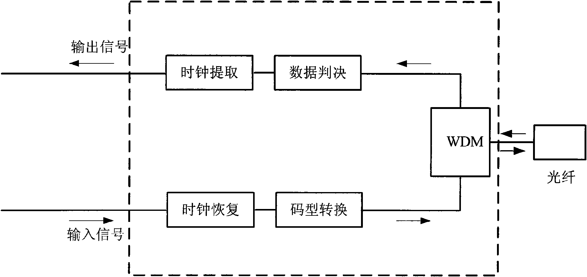
[0062] The main function of the PON interface module is to recover the clock ...


PUM


Abstract

The invention discloses a free space optical communication device based on a passive optical network (PON) technology, which aims at the situation that the current free space optical communication system is operated in an SDH system and is not suitable for a PON broadband access network technology. The free space optical communication device comprises a PON interface module, an optical emitting module, an optical emitting antenna, an optical receiving antenna, an optical receiving module, a system control module and an alignment module, wherein both the optical emitting module and the opticalreceiving module adopt infrared lasers with different wavelengths, which are respectively light with the wavelength of 850nm and light with the wavelength of 20nm, and the interference resistance andthe stability of the system are strengthened; the optical emitting module and the optical receiving module perform the transmission and the receiving by four beams of light and drive the lasers in a receiving channel by applying corresponding narrowband interference optical filters and a double-end pulse interval modulation drive circuit; the interference resistant effect of the device on severe weather is strengthened, and the device can be more favorably applied to the wireless communication of a Chinese PON broadband access network.

Description

technical field [0001] The technical field of this device is the field of passive optical network (PON) and free space optical communication, especially a free space optical communication device based on passive optical network, an optical transmission module and a passive optical Free-space optical communication methods for networks. Background technique [0002] Free Space Optical Communication (FSO for short), also known as wireless laser communication, is a way to achieve point-to-point, point-to-multipoint or multipoint-to-multipoint voice, data, and image information in an atmospheric channel through lasers. two-way communication technology. The free-space optical communication system in a broad sense includes interstellar communication and inter-atmosphere communication, and the free-space optical communication system in a narrow sense refers to wireless transmission between atmospheres. As one of the top ten telecommunications hotspot technologies today, FSO has th...

Claims


Application Information

Patent Timeline
Patent Type & Authority Applications(China)
IPC IPC(8): H04B10/10H04B10/12H04B10/24H04B10/04H04B10/06H04B10/11
Inventor 朱万华
Owner 朱万华
Learn More