Wind driven electric power generator
A technology for wind power generation devices and windmills, which is applied to wind turbine components, wind energy power generation, wind turbines, etc., can solve problems such as the increase in internal temperature of heat generation, and achieve the effect of improving reliability and durability.
- Summary
- Abstract
- Description
- Claims
- Application Information
AI Technical Summary
Problems solved by technology
Method used
Image

Examples
no. 1 approach
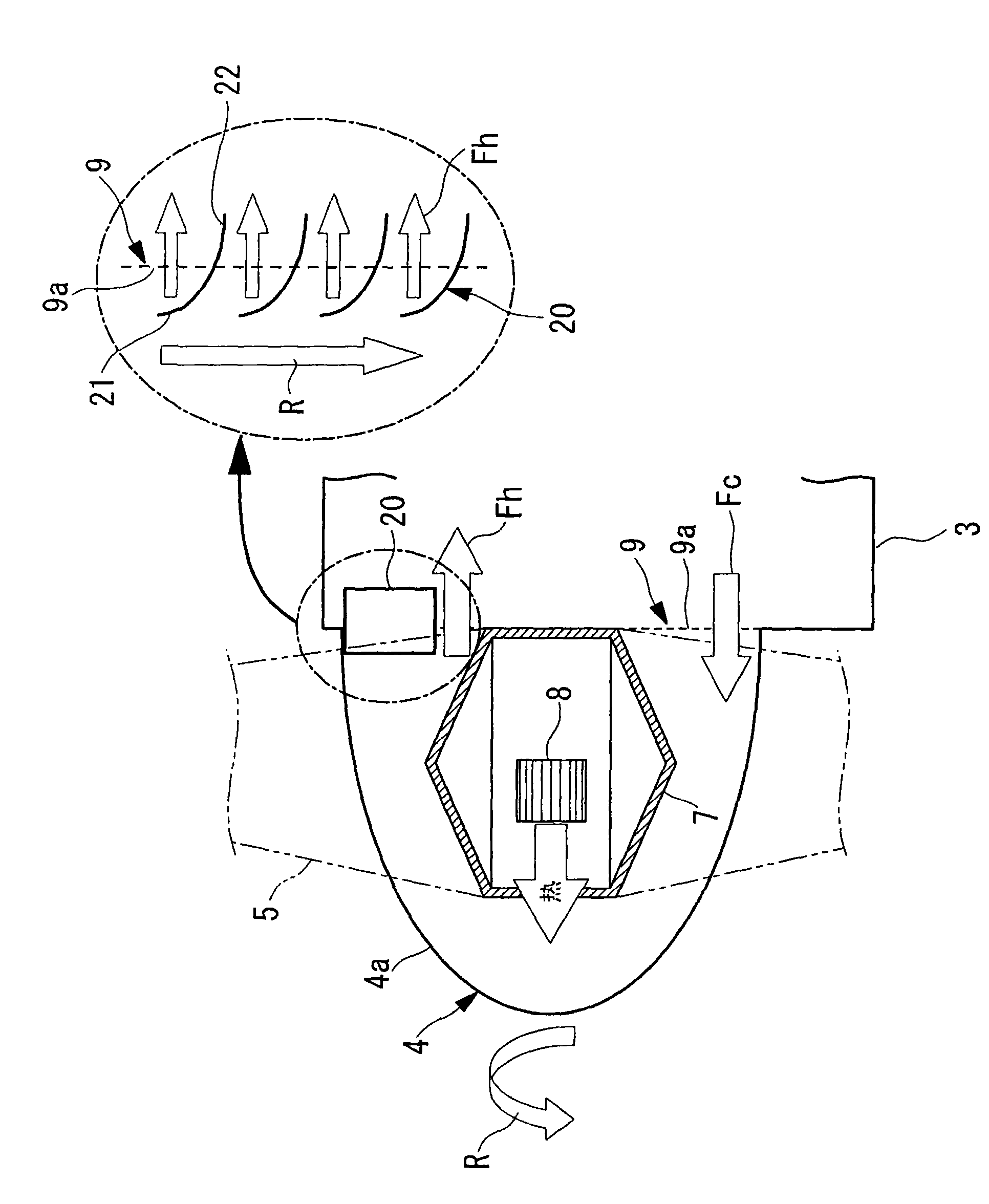
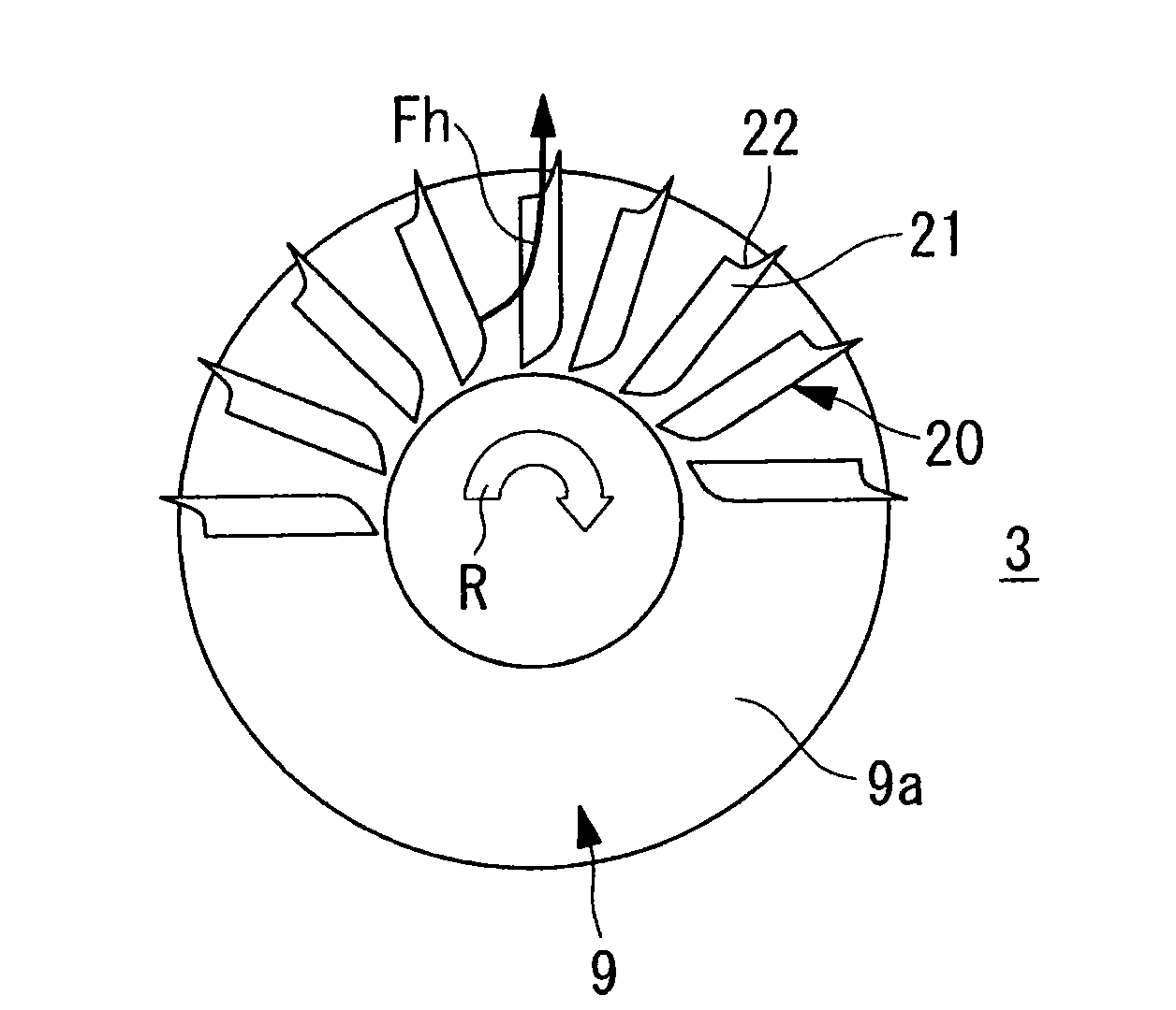
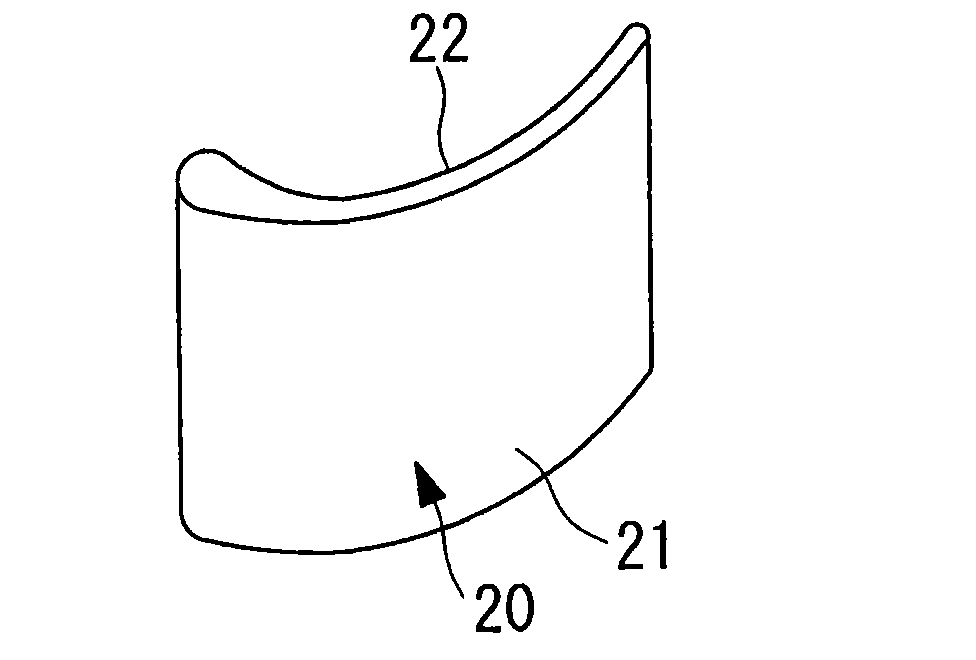
[0085] in from Figure 1 to Figure 3 In the first embodiment shown, the air flow forming mechanism for forming the air flow is used as an air circulation guide 20 (hereinafter referred to as "guide") provided in the communication path 9, and the guide 20 is, for example, image 3 The illustrated wing-shaped members are arranged in a plurality of pieces at equal intervals approximately halfway along the circumferential direction of the circular communication passage 9 . In the illustrated structural example, the guide 20 is attached along the upper half circumference of the communication path 9 (hereinafter referred to as "upper region"), but this is not particularly limited. In addition, in image 3 In the shown wing shape of the guide 20 , the symbol 21 in the figure is the back, and the symbol 22 is the belly.
[0086] exist figure 1 and figure 2 In the illustrated structure, a plurality of guides 20 are attached to the nacelle 3 on the fixed side. That is, the spacer...
no. 2 approach
[0096] Next, according to Figure 7 and Figure 8 A second embodiment of the present invention will be described. The same reference numerals are assigned to the same parts as those in the above-mentioned embodiment, and detailed description thereof will be omitted.
[0097] In this embodiment, a partition member 9b such as punched metal that partitions the communication port 9 is attached to the rotor head 4 side. An air circulation guide (hereinafter referred to as a “rotation guide”) 20A is attached to the communication passage 9 as an air flow forming mechanism for forming an air flow. The rotating guide 20A adopts, for example, a image 3 wing-shaped member as shown or as Figure 4 The illustrated wing-shaped curved plates are provided at equal intervals approximately halfway along the circumferential direction of the circular communication passage 9 . In addition, in image 3 In the illustrated wing shape of the rotary guide 20 , the symbol 21 in the figure is the ...
no. 3 approach
[0106] Next, according to Figure 9 and Figure 10 A third embodiment of the present invention will be described. In addition, the same code|symbol is attached|subjected to the same part as the above-mentioned embodiment, and the detailed description is abbreviate|omitted.
[0107] In this embodiment, both the nacelle 3 and the rotor head 4 are divided, for example, in the radial direction, and partition members 9 a , 9 b such as punched metal for partitioning the communication port 9 are attached. In the illustrated example, the communication passage 9 is provided with a spacer member 9 a on the substantially outer half of the nacelle 3 side, and a spacer member 9 b is attached to the substantially inner half of the rotor head 4 .
[0108] The airflow forming mechanism in this case uses the guide 20 described in the above-mentioned first embodiment in combination with the rotary guide 20A described in the second embodiment. That is, on the outer peripheral side of the comm...
PUM
 Abstract
Description
Claims
Application Information